Nice. So I'm talking about a cascoded gain stage properties (in isolation), while I am told about the loop gain of a blameless amplifier, including a cascoded VAS with a current source load, and then wondering why the LF gain and the PSRR increases. Talking about an apple to apple comparison... This thread deserves to be renamed to "ADD effects in audio".
C'mon Waly!
You can't load a cascode the way you did with a 20k resistor and not expect it to have a massive impact on response.
😀
🙂
Richard,
No TPC is not on my website yet. I'll post something here a little later (another hour or so).
TPC is shown to work in my SIMs, but I have not tried it on a practical amp - so this is still concept stuff. The schema I will post up also has AFEC and you can see the benefit of it as applied to CFA in distortion and PSRR.
However, I am doing it in the spirit of learning - I do not want to labelled as self promoting.
Some of my problem is more to do with how to apply 'advanced' compensation to a symmetrical amp rather than just CFA...
I have had a think about this since I saw Edmond's SuperTIS.
I am inclined to try to do what I would call "Normalization" if I still worked in Database.
In other words, unify the duplicated items, compensation components in this case. Does this make sense to you? or anyone?
There can be some issues to measure Return Ratio correctly in simulation.
So far I just make minor modifications to the circuit, not a strictly perfect solution but simple.
Hurst did a paper on correct measurement of push-pull circuits that is probably theoretically neater.
Best wishes
David
Andrew. Everyone appreciates the spirit in which you post. Or if they don't then their opinion isn't worth much.
Last edited:
Nice. So I'm talking about a cascoded gain stage properties (in isolation), while I am told about the loop gain of a blameless amplifier, including a cascoded VAS with a current source load, and then wondering why the LF gain and the PSRR increases. Talking about an apple to apple comparison... This thread deserves to be renamed to "ADD effects in audio".
It should rather be called " how to find excuses to stay in denial"..😉
If you had really read what i wrote you would have noticed that :
I re did the sim with MichalKiwanuka generic schematic .
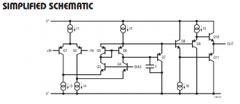
Let s use a cascode in isolation.
You notice that there s a buffer that allow to implement
a DC FB with a high input impedance that will be of sufficently
low influence over the circuit effective output Z as to not
render the sim dependant of unwanted influences as in your
schematic.
The sim is made with and without Q2 , that is , it s removed
on one case and CE is replaced by a short circuit.
That s the only difference between the two curves.
Attachments
I am inclined to try to do what I would call "Normalization" if I still worked in Database.
In other words, unify the duplicated items, compensation components in this case. Does this make sense to you? or anyone?
Do you mean simplifying symmetrical compensation where if you can reduce the component count by combining items? If so, this is what has been done in Edmond's DTMC (MCP amp) where, for example, R20 and C5 can be split to make DTMC look totally symmetrical.
This is what I had to do to understand DTMC.
OR have I totally misunderstood? Quite likely for my challenged mind.
which is the core of my argument that CFA isn't necessarily the be-all end-all audio power amplifier design approach
it is the limitations of the power output stage that is most important so it doesn't matter if CFA or some other technique made for "perfect" preceding differencing and gain stage
the limits of global or output inclusive loop gain that can be applied are limited by the output stage speed, distortion by AB output nonlinearity, output stage driving impedance nonlinearity
if Richard Marsh has too little patience for typical forum give and and take, diversions – perhaps he should Blog his cm/cfa storyline instead diyAudio - Blogs
Hi JCX,
I agree with you. However, I also admit that I was perhaps a bit quick to suggest we just replace the output stage with a perfect buffer. As pointed out above, The CFA and VFA may in some ways not be as adept at driving a less-than-perfect output load.
Maybe the way to level the playing field is to choose a common output stage for the comparisons that are made. The details of what common output stage to choose may not be extremely important, but I would suggest a good one, since the objective here is to evaluate whether CFA or VFA is best at implementing REALLY good amplifiers. I would also suggest the common output stage be BJT, since there are more of them in use and we may have better confidence in their models. There are many possibilities, but I would lean toward an output Triple, probably a Locanthi T circuit. Finally, comparisons will be difficult to make unless at least for the output transistors the same models are used. I know this is a tall order and still leaves a lot of wiggle room for comparisons to not be as apples-apples as we would like.
Cheers,
Bob
It should rather be called " how to find excuses to stay in denial".
Ok. I'm a poor student with zero experience and almost no knowledge in circuit theory and practice. I bow my head in front of the great gurus wahab and manso, and can't wait to further quench my knowledge thirst at the spring of their infinite wisdom. I promise to never post any messages that may challenge their knowledge and understanding as I will always be, beyond any doubt, wrong to begin with. Instead, I will stare at the ground and drool.
Happy now?
Here are some circuits to play with.
The qx does about 10ppm at 325W, while the kx is a whole lot worse until you change the AFEC resistor to 120 Ohms, and then you get quite good peformance.
Both the circuits close the loop at 2-3 MHz
Again, let me stress these are 'bread board' circuits and optimazation has not been completed.
The qx does about 10ppm at 325W, while the kx is a whole lot worse until you change the AFEC resistor to 120 Ohms, and then you get quite good peformance.
Both the circuits close the loop at 2-3 MHz
Again, let me stress these are 'bread board' circuits and optimazation has not been completed.
Attachments
Do you mean simplifying symmetrical compensation where if you can reduce the component count by combining items? If so, this is what has been done in Edmond's DTMC...
The idea was not primarily to reduce component count but to ensure that there are no paired components that should match, because they never will in real life.
For instance.
The simple complementary IPS/VAS produced by the "reflection" of an LTP and push-pull VAS (Bob Cordell p. 137) has paired miller capacitors, one for each side of the VAS. This introduces the known problem of "VAS versus VAS" when they both try to set not quite identical potentials at their outputs.
A "normalized" scheme would set the compensation around both sides with one capacitor so there is no duplicated parameter to mismatch.
Part of the reason some people (like Bob) are not keen on symmetrical IPS.
I am torn between symmetry and avoidance of duplication, and Edmond's SuperTIS seems a clever step towards a resolution. I have a few developments on the theme too.
Perhaps this is just a database analyst's way to look at the problem, I hope it is a clear?
Best wishes
David
David,
That makes perfect sense to me. The VAS vs VAS fight due to compensation is something I hadn't even considered. I thought it was a simplification thing alone.
I don't know whether it is relevant but potential problem I thought about with this normalised scheme (Edmond's DTMC) was that it provided a high frequency path where both sides of the amp would be effectively shorted together. What's your thoughts on this?
Didn't like that idea so went with non normalized. Also, made PCB layout easier especially if going with the cherry scheme of running the power rails down the centre of the PCB.
Paul
Ok. I'm a poor student with zero experience and almost no knowledge in circuit theory and practice. I bow my head in front of the great gurus wahab and manso, and can't wait to further quench my knowledge thirst at the spring of their infinite wisdom. I promise to never post any messages that may challenge their knowledge and understanding as I will always be, beyond any doubt, wrong to begin with. Instead, I will stare at the ground and drool.
Happy now?
We , Manso and i , are not really linked to EEnginering ,
actualy we are shoemakers , really , and our modest
ambition was only , in the waiting of godot , to help
you fix your issues with your reluctant shoes....
Well, I've replaced my new VAS with a cascoded CFA frontend, running the same 100W into 8Ohms configuration, using the same buffered MOSFET outputstage.
In comparission, I don't see anything that has improved over my VAS. The loopgain is much lower. I could get it stable easily, but THD results were an order of 20 worse than with the LTP/VAS combo. I have to admit that I haven't tried a more elaborate compensationscheme.
But what I feel it boils down to, it's the output stage and the compensation method are the definitive factor.
______________
Mr. Marsh, thank you for your kind offer. I'm doing some very casual design work on a fancy mike and may also convert the carcases of 3 PA amps into one good one before the end of the Millenium. Supa dupa discrete OPAs don't really figure in either plan.
May I pass on your offer to Linuxguru who is presently making up examples of both SWOPA & JFET990?
______________
Hi Richard over there --
If you have a CMA of any type and it is built, i'll test it. Ditto SWOPA/jFET990 line amps as a comparison of SOTA VFA for audio apps. But, the VFA's have to be already built/loaded.
I'll be in Asia a lot more often and longer after Feb of next year as i will be able to move into and furnish my new condo there and have access to company equipment/facilities. Downtown Bangkok... centrally located in that part of the 'emerging' world. Not that far from the land of Oz 🙂
Centrally located between India, China and Australia. The new Golden Triangle. Everything of interest is a shorter trip.
-Richard over here.
Last edited:
Hi all.
I have difficulties keeping up with the pace of This thread.
But i find it very interresting an i will post an schematic of my design which have been succesfull.
I hope it is usefull. By the Way, it is stable without output inductor.
I have difficulties keeping up with the pace of This thread.
But i find it very interresting an i will post an schematic of my design which have been succesfull.
I hope it is usefull. By the Way, it is stable without output inductor.
The idea was not primarily to reduce component count but to ensure that there are no paired components that should match, because they never will in real life.
For instance.
The simple complementary IPS/VAS produced by the "reflection" of an LTP and push-pull VAS (Bob Cordell p. 137) has paired miller capacitors, one for each side of the VAS. This introduces the known problem of "VAS versus VAS" when they both try to set not quite identical potentials at their outputs.
A "normalized" scheme would set the compensation around both sides with one capacitor so there is no duplicated parameter to mismatch.
Part of the reason some people (like Bob) are not keen on symmetrical IPS.
I am torn between symmetry and avoidance of duplication, and Edmond's SuperTIS seems a clever step towards a resolution. I have a few developments on the theme too.
Perhaps this is just a database analyst's way to look at the problem, I hope it is a clear?
Best wishes
David
Hi Dave,
You are exactly right. Any kind of complementary VAS that depends on two matched Miller capacitors can incur the VAS fighting issue. This is one reason why I sometimes like MIC compensation.
Cheers,
Bob
Here is it.
http://sitosite.dk/amps/miranda1v11-komponentliste.pdf
http://sitosite.dk/amps/mirand-a1a.pdf
The enable circuit does not function 100%. So there is a small startup dc spike.
http://sitosite.dk/amps/miranda1v11-komponentliste.pdf
http://sitosite.dk/amps/mirand-a1a.pdf
The enable circuit does not function 100%. So there is a small startup dc spike.
Hi Dave,
You are exactly right. Any kind of complementary VAS that depends on two matched Miller capacitors can incur the VAS fighting issue. This is one reason why I sometimes like MIC compensation.
Cheers,
Bob
The problem I see with the MIC like in your book is that if it isn't symmetrical doesn't it run the risk of asymmetrical loading on the VAS?
I have tried running it from the driver / pre driver output in sims but have found stability a problem.
Please bear in mind my inexperience.
Edit: Sonnya - looks interesting. Got as far as the VAS and lost it. Will have to have another look when I have some more time.
Last edited:
CFA & VFA
Just a thought. Would it be possible to combine both types into 1 Amp ? For eg,
1 - Two input stages connected to the next stage/s, one with VFA & the other with CFA ?
2 - Nested Feedback where @ least one stage is CFA & the other VFA ?
Best of both worlds 🙂
Just a thought. Would it be possible to combine both types into 1 Amp ? For eg,
1 - Two input stages connected to the next stage/s, one with VFA & the other with CFA ?
2 - Nested Feedback where @ least one stage is CFA & the other VFA ?
Best of both worlds 🙂
Just a thought. Would it be possible to combine both types into 1 Amp ? For eg,
1 - Two input stages connected to the next stage/s, one with VFA & the other with CFA ?
2 - Nested Feedback where @ least one stage is CFA & the other VFA ?
Best of both worlds 🙂
Dont think so but you can combine 2 CFA frontends in a VFA amp. It displays the slewrate and bandwith of CFA, the dc accuracy of VFA at the expense of complexity and noise penalty. Noise is usually worse than CFA but this depends on design. Its in use in marantz top of the range amps and preamps. LM6171 and LT1468 are opamp examples.
- Home
- Amplifiers
- Solid State
- CFA Topology Audio Amplifiers