I know all this but now take a non cascoded VAS using a given
device , say a BC546 for instance , check the OLG of your
amp and then cascode said VAS using also a BC546 as
common base device , gain will increase substancialy
even if there s about the same early voltage for
the common base device as for the single non cascoded
common emitter.
This say that it s not only the emitter/collector residual resistance
that is at work for gain limitation of the single device VAS but
also the collector/base parasistic resistance , r.mu , wich can
also be the limiting factor of a cascode output resistance
if ever it s smaller than the collector/emitter resistance.
Using the exemple above of two same devices to implement
a cascode , PSRR is improved by 6dB when cascoding the VAS.
Please play with this calculator and comment the results you get. The gain is (Rc||Rl)/Re with or without the cascode.
Cascoding doesn't improve the PSRR, not even by 0.1dB, current sources may do so.
current sources may do so.
I would have thought this would be frequency dependent.
Please play with this calculator and comment the results you get. The gain is (Rc||Rl)/Re with or without the cascode.
Not true , the simulator say otherwise , that said , of course
that the gain can be (Rc||Rl)/Re if you neglect other parameters...🙄
Using the same device to cascode a basic VAS CAN increase gain A LOT
and i have explained why in my previous post.
Notice that i didnt invent this explanation , it is documented
but some people think that what they dont know doesnt exist...
Cascoding doesn't improve the PSRR, not even by 0.1dB, current sources may do so.
The simulator says otherwise , the same circuit exhibit
6db better PSRR when cascoding the VAS as only modification.
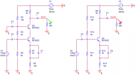
An exemple using BC546 as VAS and cascoding element.
Attachments
Not true , the simulator say otherwise , that said , of course
that the gain can be (Rc||Rl)/Re if you neglect other parameters...🙄
Using the same device to cascode a basic VAS CAN increase gain A LOT
and i have explained why in my previous post.
Notice that i didnt invent this explanation , it is documented
but some people think that what they dont know doesnt exist...
The simulator says otherwise , the same circuit exhibit
6db better PSRR when cascoding the VAS as only modification.
An exemple using BC546 as VAS and cascoding element.
At this point, this sounds like our own Samuel Beckett work. So absurd it became interesting!
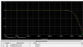
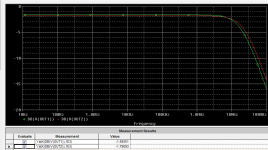
You simulated an unspecified circuit and posted some mysterious results that contradict the elementary knowledge and the common sense. Because you seem to prefer a simulator over your own brain, I'm playing your game and here it is (schematic, gain, PSRR). 0.2dB differences in gain and PSRR between the non-cascoded and the cascoded versions of the same gain stage (two identical devices, which is another absurd idea). Yes, my determinations by inspection were wrong by 0.1dB.
Sleep over it, good night.
Attachments
Last edited:
At this point, this sounds like our own Samuel Beckett work. So absurd it became interesting!
I told you , you deem as absurd what you cant grasp..
You simulated an unspecified circuit and posted some mysterious results that contradict the elementary knowledge and the common sense.
You should know the only way it can be simulated but since you
dont want or voluntarly elude the thing i ll explain you what
and i how i did it , wich bring us to your next point or rather
lack of if we except the usual straws and arrogant postures.
Because you seem to prefer a simulator over your own brain,
I'm playing your game and here it is (schematic, gain, PSRR). 0.2dB differences in gain and PSRR between the non-cascoded and the cascoded versions of the same gain stage (two identical devices, which is another absurd idea). Yes, my determinations by inspection were wrong by 0.1dB.
Sleep over it, good night.
To use a simulator one has to have a brain , isnt it , and even
more brain to use an adequate circuit that will display said
caracteristics and not a flawed circuit that just show that
you have no idea of how to do the accurate simulation.
No one in his right mind would use a circuit where all the
parasistic resistances are neutered by low value external
resistors that have lower values than the said parasistic
resistances and then claim that he proved that thoses
parasistics effects are inexistant or the result of imagination.
The VAS must be implemented as it would
be in a real functional amplifier where it can have very
high output impedance while your nonsensical schematic force
the output impedance to a mere 4K at best.... hence , you
will see nothing and then run to write yet another useless post ,
at least on the subject i m talking about.
If you had looked and understood the curves , seeing the increased
gain at low frequencies would had given you some clues , that is ,
a VAS has very high output Z at low freq. , hence if gain increase
it means that the parasistic loading resistors effects , wich will limit
output Z and gain at DC have been forcibly reduced by just cascoding
with the same element.
Take the usual topology , differential + VAS , and re do your sims ,
but please , no more of those truncated circuit and useless comments
once you think someone is wrong , it bring nothing to the debate
that otherwise would be more fruitfull if ever it was.
I didnt need to, Wahab did that and confirmed the workings and THD or did you miss that.
He knows it since he used it as exemple to make some
basic explanations :
http://www.diyaudio.com/forums/solid-state/240712-cfa-topology-audio-amplifiers-50.html#post3606012
One can only wonder why so useless and unfounded rants...😕
What I don't understand is that during the extensive simulation of my CFA amp I tried the three transistor enhanced cascoded VAS. Using 2N5551/2N5401 pair and the A1381/C3503 pair in a complementary push pull VAS/TIS. I didn't gain anything with respect to THD it just simed just the same as the two transistor enhanced VAS.
If Waly's sims were correct this makes sense as there was no increase in loop gain but if Wahabs sims are correct I would have expected a reduction in THD.
Is my logic correct? I'm only a beginner in this design stuff so this is a plea for some clarification.
Given my fear of the three transistor VAS/TIS I opted to go for the plain enhanced VAS/TIS.
You are just nailing it!
Many amps nowadays dispense with cascodes because the newer trannies are good enough that you don't need it. One example of this is the e-Amp which has single digit ppm distortion at 20 kHz (VAF amp).
However, when a do my next CFA, I will cascode the front end level shifter for the flexibility it brings.
Last edited:
Wahab wrote "Using the exemple above of two same devices to implement
a cascode , PSRR is improved by 6dB when cascoding the VAS. "
Probably because you have isolated the cascodes transistor Cob from rail noise coupled in from the PSU.
a cascode , PSRR is improved by 6dB when cascoding the VAS. "
Probably because you have isolated the cascodes transistor Cob from rail noise coupled in from the PSU.
The diamond front end cascodes are also useful if going for 60v or greater rail voltage. The front end of the diamond input the transistors usually see a very low voltage but the other two transistors see a much higher voltage. This forces your choice of transistors to ones that can cope with high Vce. This then means you have to use the same devices on the input. These devices are almost guaranteed to not perform well at very low Vces.
Cascodes in this case just look like the ideal solution allows low Vce devices to be used on the back end of the diamond as well as the front. Allowing matching transistors to be used.
Cascodes in this case just look like the ideal solution allows low Vce devices to be used on the back end of the diamond as well as the front. Allowing matching transistors to be used.
Last edited:
Waly, did you consider loading effects on your 2 sims? This may have quashed the improvements that Wahab is reporting.
What I don't understand is that during the extensive simulation of my CFA amp I tried the three transistor enhanced cascoded VAS. Using 2N5551/2N5401 pair and the A1381/C3503 pair in a complementary push pull VAS/TIS. I didn't gain anything with respect to THD it just simed just the same as the two transistor enhanced VAS.
If Waly's sims were correct this makes sense as there was no increase in loop gain but if Wahabs sims are correct I would have expected a reduction in THD.
Is my logic correct? I'm only a beginner in this design stuff so this is a plea for some clarification.
Given my fear of the three transistor VAS/TIS I opted to go for the plain enhanced VAS/TIS.
I pointed in a previous post that THD wasnt improved
valuably at high frequencies but it does improve at
lower frequencies assuming that the VAS loading doesnt
crush its eventual high output Z.
I pointed in a previous post that THD wasnt improved
valuably at high frequencies but it does improve at
lower frequencies assuming that the VAS loading doesnt
crush its eventual high output Z.
I'm going back to the sims tomorrow to have another look at this. I don't think loading is an issue but I'm going to have closer look at the lower frequencies.
Wahab wrote "Using the exemple above of two same devices to implement
a cascode , PSRR is improved by 6dB when cascoding the VAS. "
Probably because you have isolated the cascodes transistor Cob from rail noise coupled in from the PSU.
I have to sort out the cause since i ve no explanation for now ,
i ll recheck to be sure to not be wrong but what is sure is the
gain increasing when cascoding despite using the same device
for the common base part , this say that with no cascode the
Early effect is not the only influence on the Vas DC gain limitation.
Waly, did you consider loading effects on your 2 sims? This may have quashed the improvements that Wahab is reporting.
I wont respond at his place but i ll point that both collector/emitter
and collector/base parasistic resistances have values well above
the 4K he used to load the output node while an usual VAS has
an output Z that can be megohms at DC , just imagine what
happen if you load the VAS of your E amp with a 4K resistor
that goes to ground , a "technic" used by low GNFB afficionados
to seemingly "extend" the OLG bandwith....
I'm going back to the sims tomorrow to have another look at this. I don't think loading is an issue but I'm going to have closer look at the lower frequencies.
At 1khz there should be quite a difference but at 20khz
there should be no remarkable improvement , at least
this is what i generaly observe when not using streched
designs with questionable stability.
At 1khz there should be quite a difference but at 20khz
there should be no remarkable improvement , at least
this is what i generaly observe when not using streched
designs with questionable stability.
Wow, you are right...
Just done a real quick and dirty sim on my current circuit and you are correct. Big difference (about 50%) at 1kHz but not a lot of difference at 20K (10% improvement).
cascode can be useful for high frequency distortion reduction as well
http://www.essex.ac.uk/csee/research/audio_lab/malcolmspubdocs/J10 Enhanced cascode.pdf
(has real workd measured results later in the paper)
but few techniques are absolute good by themselves - many times it is a "onion peeling" process - some improvements will not be visible as such until other layers of distortion or gain limitation are improved to sufficient levels
Last edited:
Yes, a 15k load on a VAS ( standard or cascode) will reduce gain by 20 to 30 dB.
I re did the sim with MichalKiwanuka generic schematic , a blameless
with enhanced cascoded VAS and the results are invariable ,
cascoding increase gain by roughly 40dB.
Without or with a driver for the VAS result in relative increasement
of the same order in respect of the initialy non cascoded VAS gain.
I post Mike s schematic and the curves for the version
with enhanced VAS , this schematic , and for the non
enhanced VAS.
Attachments
- Home
- Amplifiers
- Solid State
- CFA Topology Audio Amplifiers