Damir,
As noted in one of your threads, nice work.
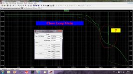
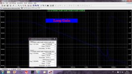
It would be beneficial to show the high loop gain, and since it's always a topic the slew rate with and without the 2nd order compensation.
With a cfa what is the motivation to encompass the input stage within a nested loop, or is there a significant advantage given its linearity to start with?
Don't mean to pile on work for you but could lead to interesting discussion.
Thanks
-Antonio
With this type of compensation I just tried to get the amp stable enough, but did not spent a lot of time on it. It should be simulated much more, and I think that this amp is to complicated, in my opinion with simpler schematic it's possible to get equal result.
But it's good startin point for discussion and suggestion.
BR Damir
Attachments
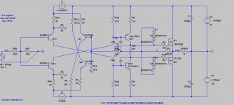
Nobody showed CFA schematic here yet. Here is one (to complicate) but with THD20k 0.001369% at 50W/8ohm, PHM is 75 degree anf GM is 13dB.
BR Damir

The high performance mirror doesnt seem to help.
How much improvement does the HEC provide the output.
Damir I ll do a quick sim of a CFA amp I was co involved with many years ago, less complex and Im pretty confident it will show better performance as measured by a japanese magazine for review it was below 10 ppm.
If your HEC circuit provides a useful improvement I m thinking of trying it instead of a triple.
HEC improvement at 20kHz with the same power output is 8.5dB, not much, in some other thread I think I've had better result.
Here I had 25dB improvement at 20kHz with HEC, but that was no GNFB amp.
http://www.diyaudio.com/forums/solid-state/238252-odnf-no-gnfb-power-amp-4.html
P.S. It looks like that the gain part(current conveyor) is not optimized.
http://www.diyaudio.com/forums/solid-state/238252-odnf-no-gnfb-power-amp-4.html
P.S. It looks like that the gain part(current conveyor) is not optimized.
You should try simple shunt compensaton to the rails. This type of compensation allows higher ULGF with CFA. Split it in two from each half of the mirror vas. Your closed loop response doesnt look good, it shows some peaking. I think its to do with the alexander type comp. I get similar response using it and I dont like it although Bonsai says it works fine for him. I cant find any THD benefit from using it either.
Next generation developement was this basic topology:

Bipolar Current-Mode Amplifiers - Translinear circuits -Currrent-Conveyers -
Thx-RNMarsh
Named current conveyors, this kind of circuits are extremely handy for many applications as they can be used with, or without, negative, or positive, feedback. For example in a small signal rectifier circuit.
They simplify many circuits and are very didactic.
They were used as current to voltage converters in Wadia CD players.
They were announced as having to soon replace conventional op-amps in many applications but they did not. The reason probably relies in :
- the weakness of the input stage having DC performance and noise and PSRR performances not as good as conventional op-amps using an LTP input.
- the higher cost of manufacturing in IC as well as in dicrete components
Input impedance would be very low, no?
In real circuits, the diode connected input transistors are generally replaced by emitter followers.
Nobody showed CFA schematic here yet. Here is one (to complicate) but with THD20k 0.001369% at 50W/8ohm, PHM is 75 degree anf GM is 13dB.
BR Damir
You could try dropping your feedback resistor network by a factor of 10 - that should improve your loop bandwidth and slew rates.
You comp cap - you should try the Alexander comp technique - this offers beneits for CFA.
You could try dropping your feedback resistor network by a factor of 10 - that should improve your loop bandwidth and slew rates.
You comp cap - you should try the Alexander comp technique - this offers beneits for CFA.
See C2, that is alexander type comp or not ??
I am sorry I am off tomorrow for two weeks vacation and I don't have internet there.
When I'm back I hope to find here a lot af good CFA amps.
Best Regards
Damir
When I'm back I hope to find here a lot af good CFA amps.
Best Regards
Damir
I need to look at your circuit more carefully. If your - 3dB bandwidth is low, Alexander comp does not really add any benefit.
Anyway, we can look again after you come back from vacation.
Anyway, we can look again after you come back from vacation.
Could-you, please, publish or send-me your sim files and models for the VSSA sims you made ?I am sorry I am off tomorrow for two weeks vacation and I don't have internet there.
Because nobody seems interested to make a VFA version of it, i could try to make one myself.
I had send-you a PM
Have nice holidays,
Christophe.
I need to look at your circuit more carefully. If your - 3dB bandwidth is low, Alexander comp does not really add any benefit.
Anyway, we can look again after you come back from vacation.
OK here is .asc file if you whant to play with it.
BR Damir
Attachments
Could-you, please, publish or send-me your sim files and models for the VSSA sims you made ?
Because nobody seems interested to make a VFA version of it, i could try to make one myself.
I had send-you a PM
Have nice holidays,
Christophe.
Here it is. Thanks for nice wishes and good luck.
Attachments
Thanks a lot Dadod. Did i need the missing supertex.txt ? or just i have to erase the entry ?Here it is.
Thanks a lot Dadod. Did i need the missing supertex.txt ? or just i have to erase the entry ?
Just erase it.
Thanks so much, Dadod.
Values adjusted to the VSSA V1.4.
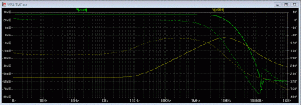
First sim:
Bandwitch: green trace.
Phase at 0db: -250° (pointed green)
Openloop bandwidth (golden trace) :14Khz !!
Feedback losses at 20Kz = -4db comparing to 100Hz. Ie ~:23db.
I have to work on a VFB version of this amp, now.
Values adjusted to the VSSA V1.4.
First sim:
Bandwitch: green trace.
Phase at 0db: -250° (pointed green)
Openloop bandwidth (golden trace) :14Khz !!
Feedback losses at 20Kz = -4db comparing to 100Hz. Ie ~:23db.
I have to work on a VFB version of this amp, now.
Attachments
Last edited:
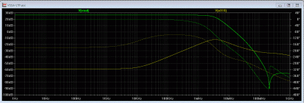
And there, a quick'n dirty LTP version of the same VSSA:
Main difference is the open loop bandwidth cutoff at 10KHz. (as expected ;-)
Phase: -206°
Wow, L.C. Both rock stable, what an amp !
Not big difference in HD at 20Khz.
Main difference is the open loop bandwidth cutoff at 10KHz. (as expected ;-)
Phase: -206°
Wow, L.C. Both rock stable, what an amp !
Not big difference in HD at 20Khz.
Attachments
Last edited:
The previous one was keeping the impedances equal. Makes crazy current (32Ma for VAS)
Once VAS reduced to 12ma, equal to the CFA version and same quiescent current in the Power fets, and input stage same currents too, i get exactly the same results when i did the same (in opposite sens) with my own amp.
Distortion at 20Khz is 3X higher in this VSSA-VFA version than VSSA.
Up to you, VFA fans, to improve-it, now, adjusting the values, but for me the die is cast : CFA has 10X the bandwitch, and 3 time less distortion at 20Kz that this VFA version.
Attachments

Last edited:
- Home
- Amplifiers
- Solid State
- CFA Topology Audio Amplifiers