Hi Guys
Nice work, Forr.
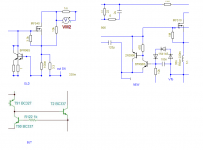
Personally, I do not see why the buffered voltage reference form of current source is still applied to any amp that aspires to speed? The feedback type CS in your bottom drawing exhibits much better speed and current accuracy as well. It is the only type I use.
Have fun
Kevin O'Connor
Nice work, Forr.
Personally, I do not see why the buffered voltage reference form of current source is still applied to any amp that aspires to speed? The feedback type CS in your bottom drawing exhibits much better speed and current accuracy as well. It is the only type I use.
Have fun
Kevin O'Connor
60 is quite conservative - many control systems are sucessful with 30 degree margin - but you do want to allow for loading and operating point variation
You didn't mention GM. I wrote elsewhere
...
I don't think we need to worry too much about circuit variability.
A proper compensation scheme will set the relevant return ratio with well defined passive components rather than unpredictable transistor parameters. 1% metal film resistors and 5% capacitors or better, probably.
So we can optimise the feedback network for best response at nominal.
We eliminate all the RHP zeros so essentially no excess phase (used strictly).
That means the frequency response is all we need to consider because it essentially defines the behaviour.
For instance the impulse response is just a transformation and will be nice if the frequency response is smooth.
The Nichols chart shows how much response peak occurs for various combinations of phase and gain difference. One curve intersects about 60 degrees (one radian) and 6 dB. So that is a balanced trade-off...
Does this look reasonable, based on your experience in the area?
Best wishes
David
My own experiments with this circuit :
Other posts show the impressive harmonic distorsion numbers and the benefit obtained by a 3 transistors Wilson current mirror.
An externally hosted image should be here but it was not working when we last tested it.
You could use that fastest chain to help what high gain chain could not do. Using asymetric dual singleton is better than that VFA mode.
Attachments
I don't believe it would be good to begin with a complicated and ultra low distortion CFA. As the idea was to explore (and compare) the evils of the two topologies (CFA and VFA). We need measurable distortion numbers.The LC circuit may not be the best reference for learning about CFA. To get really good THD even with matched parts, requires a two stage circuit, such as Andrew's and Wrenchclone's.
We could use a Nelson Pass F5 as well, but i see some advantages to VSSA.
My proposal was to explore, in a second time, how to reduce them to silence.
I'm not sure it will change a lot the listening experience, but for the beauty of numbers.
Too, i believe Richard will have two samples of this amp soon, so he can (if he wants) makes reports and measurements in real world.
But it seems he has an other idea about what to begin with. I'm sure it is a clever one. Wait and see.
Last edited:
We could use a Nelson Pass F5 as well, but i see some advantages to VSSA.
NP is a great designer. There must be things to learn from his decision to put his amps in certain "operating points". T/V/SSA are too good at very high frequency but often not good enough at low. F5 is OTOH very balanced. If this performance at lows can be achieved with sacrificing inaudible performance at high end then why not.
Aleph-J (and of course the phenomenal J2) is different topology implemented by the same designer. So the knowledge and skill to get the best out of both topologies is equal. So which one is better??? Of course I like Aleph-J more, which is a VFB.
So for me this CFA challenge is about higher power amp (class-B) than F5. At least 100W. And VSSA topology with its simplicity can do this with acceptable distortion and "acceptable" drive for mosfet output.
IMO, designers should set numbers that they want to achieve. It is sad if the designer doesn't know how the numbers should relate with audible performance, because that is the whole point imo, to choose the right strategy (including topology) to achieve the goal.
Since it's still in a theoretical phase I would suggest ideal current sources rather than bloating the individual circuits with real implementations, so the focus is purly on the parts that make up the actual amplifier.
This is a very good suggestion for simulations. Then what is going on is not obscured by unnecessary complexity.
Cheers,
Bob
And there is an actual issue that plagues both CFA and VFA topologies: The dreaded slow output stage 😀 I don't think there are extremely high Ft lateral FETs around. Perhaps better chance with the verticals, but that comes with its complex temp compensation scheme.
Why are you suggesting that vertical MOSFETs require a complex temperature compensation scheme? Verticals need no more complexity than the usual Vbe multiplier found with BJT output stages, and are more stable with it than BJTs. Are you suggesting that the simple Vbe multiplier is "complex temperature compensation"?
Cheers,
Bob
Hi Guys
Wrenchclone, your schematic in post-119 needs buffers between the VAS and mosfet gates. Lots of capacitance there to slew and slow things down. I suspect that is the slew-rate bottle neck in your circuit.
Bob, I've never built an amp that needed a servo to set the DC offset. To me, servos seem like a "bandaid" on either a poor design or to accommodate a poor decision. Why do you need DC response? You can't hear zero hertz and your speakers will die from it. The servo craze peaked back in the 1980s with all those DC-to-greenlight amps from Japan - great specs, but "DC"?
I've built a few amps using an input section like your mosfet amp, except with BJTs instead of jfets right at the input. No servo. You state "servo not shown" in a later form of that schematic in your book.
I like gain that rolls off DC and have no problems using a high-value cap to achieve this. I've built CFAs with AC coupled feedback and had no DC offset issues nor need for adjustments even without matched devices. When everything is matched, there is no current through the shunt element of the feedback loop anyway.
A point I make regularly is that every opamp output and DC amplifier output should have a resistive tether to ground. Adding one simple inexpensive part helps the circuit establish low DC offset much more readily. App notes tend to be stripped of nearly everything required to make them work in the real world, and then the legacy of poor design grows...
Andrew's nx and sx amps work pretty well and follow the basic simplicity RNM desires while attaining pretty good performance.
The LC circuit may not be the best reference for learning about CFA. To get really good THD even with matched parts, requires a two stage circuit, such as Andrew's and Wrenchclone's. As an aside, the number of stages in CFA may be couned differently than for VFA - not sure. An ambiguity occurs in Walter Kester's "High Speed Operational Amplifiers" treatise, written for Analog Devices, where both the "basic CFA" and "2-stage CFA" look the same except the latter shows the three compensation caps.
Most claims of "good sound" from builders merely reflect the satisfaction of building anything that works first, and does not sound horrible right out of the gate. The first amp I ever built only had a response to 37kHz, but it was a learning experience mostly in how to make such measurements with a scope. That thing never passed being a hair ball of tacked together parts, but it worked. The only amp I built that blew up was a 100W app from Motorola. The latter actually made sound before it blew up, which was not bad, so satisfying in its novelty; never heard the hair ball.
When I mentioned the use of CFPs previously, it was for the input conversion circuit as a possible means to reduce the impedance error at the feedback node.
An alternate input circuit - which may be cast aside by y'all without comment - is one I built around 1990. It uses comp-diffs driving comp EFs in a unity buffer arrangement. I used 5-pin SIP diff and CM packages, so wiring was dead simple. The goal was just to have a very wide bandwidth buffer. This would be most akin to Doug Self's (is his name okay on this thread? hehe) discrete opamp buffer, shown in the Small Signal Audio Design book, achieving 4ppm THD up to 10kHz (fig.3-17e). His uses a single diff, CM, single EF and current sources, with usual Cdom.
With whatever input stage becomes "acceptable", I think it is worth looking into bootstrapping it so that Early effects are minimised. It depends on whether such a method saves parts or has better effects than cascoding everything in sight. The above buffer circuit example has the advantage of <2mV offset between input and output, so as a CFA input stage, the NFB node would be pretty low-z as another loop monitors it.
I am happy to escape miller compensation and CFA easily does that. Even if required for high-frequency stability, it does not come into play until well above the hifi band.
Have fun
Kevin O'Connor
Hi Keven,
Is there a misunderstanding here? A DC servo does not provide a DC response any more than a capacitor approach does, and an extremely low-frequency response is not the reason why a DC servo is used. It is a very effective way of eliminating the dreaded electrolytic capacitor in most cases. Or, worse yet, a DC offset pot.
As long as one can design an amplifier with output DC offset less than, say, 20mV without resort to an electrolytic capacitor, a large quality film capacitor, a trim pot, or a DC servo, then that is fine. Otherwise, one must pick their poison. We all make different choices in that latter regard, but my preference is to use a DC servo.
Can you be more specific about the problems you see with DC servos?
Cheers,
Bob
That the point of all the controversies in audio: Nobody knows exactly.It is sad if the designer doesn't know how the numbers should relate with audible performance...
As i said somewhere else, if my ears are not able to hear any more 18 000 Hz sin waves, i clearly notice any changes due to a notch filter at 40Kz (that i used, sometimes, to bring air in some female voices). Phases ? Increase of transient levels ? Added agreeable TIM distortions ?
I believe (how to prove ?) our ears are VERY sensitive to energy. And, even if the differences between two signals are in high order harmonics out of our range, the surface change of the wave is noticeable.
I make the comparison with the way our eyes work. We are sensitive to movement (for our survival), and, when it can be difficult to notice a fly sitting on a surface, you immediately see-them when they fly.
Of course, we have to avoid very bad numbers in harmonic distortion. Near everybody notice a difference with high order distortions differences out of the audible range. And harmonic distortion is a little part of the story: we are listening to music, made of transients. We measure standing waves. In the active devices (temperatures) it makes a big difference.
Well, nowadays, we are able to sample before/after musical signals and print the differences. But this gives no informations to how and why.
If audio design was easy to measure, a program would be perfect for a perfect design, and this forum could close itself.
That is the reason why, if i was on the objectivist side when i was young, i use more and more my ears to make my opinion. With all the difficulties involved, memory, tendency to fool myself, various sources qualities, placebo effects....
That is all the question of this topic. We are several to find differences in our listening experiences between CFA and VFA. And something constant in presentation. A character difference. We are several to prefer CFA, like R.M said: "Personally, I dont care about VFA anymore. Thats a done deal. Well understood." While they can behave worse in HD, and the other measurable differences are far away out of the audible range.
I don't think neither R.M, pretend they are better for you (neither me): Everyone is free to prefer VFA.
All the interest of this thread is to figure out the differences, and try to correlate those with our listening experiences.
And learn how to improve both topologies.
Is a DC servo behave really differently from a cap multiplier, i mean replacing a poor lytic cap (in Hf, due to its inductance) by a better film cap ?I like gain that rolls off DC and have no problems using a high-value cap to achieve this.
Well, it is parallel instead of serial, but what the hell ?
Last edited:
DC servos has been discussed before have a look here:
http://www.diyaudio.com/forums/solid-state/3754-dc-servo-output-drift.html
http://www.diyaudio.com/forums/solid-state/3754-dc-servo-output-drift.html
So for me this CFA challenge is about higher power amp (class-B) than F5. At least 100W. And VSSA topology with its simplicity can do this with acceptable distortion and "acceptable" drive for mosfet output.
IMO, designers should set numbers that they want to achieve. It is sad if the designer doesn't know how the numbers should relate with audible performance, because that is the whole point imo, to choose the right strategy (including topology) to achieve the goal.
Choose the one that has best sounding. Which one is best of yours?
What if the number is misleading or what if better number sounded worse?
The numbers are so many.
What does it look like?
First off lets get a show of hands. Show me what you think the topology is for a CMAmp. Just the basic structure that meets all the characteristics outlined.
[just fb to a low z port isnt it. The current-feedback concept is by no means new. The technique can be traced at least back to W.R.Hewlett, who used cathode feedback in 1939 to design his now famous sinewave oscillator.]
THx-RNMarsh
Diamond buffer as subtraction node is not an option. Never like them anyway, tend to be 'nervous' at HF and the sound is consequently 'erased' like. 
The best is modulation (input-FB signal) of the same (one) linear part (in its most linear area) with gain. So the input stage must be of the best possible topology and materials what market can offer. From than on it is trivial. 😉
Also do not forget about importance of the PCB layout, as this is the last but very important 'component', never considered by the simulating SW. Top level CFA must have double layer SMD filled PCB, with shortest possible tracks especially around the input/VAS-TIS and feedback loop of course. Lately I saw only few PCB designes matched this quality level: Sonnya's TSSA, Bigun TGM7, CBS240 Mosfet amp, ChocoHolic SystemD_2kW and not to be too modest VSSA/First One. 
Would like to add that, as the distortions induced by the non constant parasitic capacitances in the input transistor are never canceled by the feedback loop, there is benefit to reject their influence far away: Both keeping feedback loop impedance as low as possible, and filtering the input signal by a lowpass filter as low as possible. Adding a (good) capacitance to the ground at the input (tricky). Right ?So the input stage must be of the best possible topology and materials what market can offer.
This will make a closed amplifier with an impressive bandwidth to look very limited. Good for the ears, not for marketing 😉
Marketing guys will ask for slew rate measurements if they understand.
DC servos has been discussed before have a look here:
http://www.diyaudio.com/forums/solid-state/3754-dc-servo-output-drift.html
Thanks for the reference; I had not seen that thread before.
The slow movement of a few mv or so that they mention there is infrasonic noise that results from slow variations in the mains/voltage rails, and gets through to the amplifier output due to finite PSRR. You will get this same infrasonic noise if the amplifier is truly DC coupled and DC offset trimmed.
This infrasonic noise is not a result of the DC servo. If one used the conventional electrolytic capacitor in series with the feedback shunt resistor instead of the servo, and its LF corner was the same as that of the servo, the same infrasonic noise would be observed.
Often the use of the DC servo results in a lower LF corner than what people achieve with the capacitor, but this need not be the case. You can set the DC servo's LF corner to whatever you want.
A good low-noise audio-quality JFET op amp should always be used for the DC servo integrator. A quality film capacitor between 0.1uF and 1.0uF should be used for the integrator. See the DC servo design discussion in my book in chapter 8.
There should be no static temperature-dependent offset if the DC servo is properly designed with a decent op amp. The input offset voltage of the op amp controls the amplifier DC offset, and it should not vary much with temperature. If you use a BJT op amp for the servo integrator (not a good idea), its input bias current may cause some drift under some conditions.
Cheers,
Bob
Hi Guys
Bob, I have no confusion about what a DC servo does or how it works. I would just rather not have an opamp in the feedback loop or creating an alternate loop. To me, just as you stated, the basic amplifier should exhibit a low offset by design.
To that end, I think that either an "enhanced" form of the usual diamond input stage for CFA, or an alternate diff-based input stage should be used to build the input buffer. The latter has all of the usual benefits of the diff for good DC balance even without matched parts. It may be that for the performance the "CFA committee" decides it wants from this thread's design disallows a diff front end? I was just making a suggestion for ways to improve the front end, and a small plea to come up with a design that does not need a servo to have acceptable DC performance.
The design in post-173 is along the line of what I was thinking as a good start. It is more complex than Andrew's, which someone already objected to as a "too complex" beginning as well.
Maybe there is a division of interest here inasmuch as some builders want a fully symmetrical circuit and others want something SE at least at the front end? Rod Elliot has a singleton-input amp as his CFA example. It works okay and may have acceptable performance for some. Andrew's nx and sx amps are pretty simple - no current mirrors or current sources, just 10 Qs altogether; Rod's circuit has 6 Qs. You can easily get "bad" performance from either circuit and then see how to make it better, but why reinvent the wheel? Learn from the lessons provided. Debate the virtue of the reasoning behind the designer's choices. Suggest alternate methods. Discuss what might be an improvement.
Have fun
Kevin O'Connor
Struth none of these are optimal, poor input stages with no voltage gain. I suggest VSSA input stage elevated with super beta, super linear, low noise compound BJT's pair, each of the two made out of three to four single BJTs. Input current injection made by ultra high Z CCS. Now that would make some difference indeed. My CSA in that topology is already working on my test bench.
- Home
- Amplifiers
- Solid State
- CFA Topology Audio Amplifiers