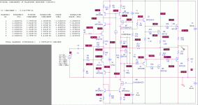
BTW -- any one see something else in the schematic that is/was new (at that time)?
-RM
CCS in emitter instead in collector?
if this brave preamp sounded good that means that THD is not good tool for estimating of the quality of the amps.
I had to add Miller caps to stabilise it.
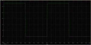
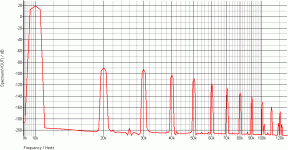
with output voltage as shown had thd ~0.7%
with output voltage 2Vpp thd was ~0.4%
comparing its thd to Dadod's no gnfb thd looks very poor (http://www.diyaudio.com/forums/solid-state/235695-no-nfb-line-amp-gainwire-mk2.html) but I guess that thd is bad thing for comparing the quality of the amps😕
Somewhere there is something wrong with that circuit, I have similar one but without input cascodes that achieves below 100 db THD with heavier loads.
CCS in emitter instead in collector?
No. Thats not it.
I introduced another idea.... the preload (1.2K from supply to ground) on the three terminal reg (LM317/337). Why and for what benefits gained?
Thx-RNMarsh
Last edited:
Somewhere there is something wrong with that circuit, I have similar one but without input cascodes that achieves below 100 db THD with heavier loads.
Dont need the cascode for low distortion... I thought that was a point made... it was only added later there to increase PSR and CMR.
Now then, show us a more optimized version one or your similar one. Mine was just an exercise and proof of concept back then.
Thx-RNMarsh
Last edited:
I've been pecking away at the circuit shown in post #119, with some improvements. Per R. Marsh's observation, a follower was added between VAS and output stage. This made the amp much faster, and gave me a lot more freedom in choice of compensation, as the the output mosfet gate capacitances no longer dictated the dominant pole.
I got some improvement in harmonic distribution by using mosfets rather than BJTs for cascoding the VAS.
Cascoding the JFET input stage yielded significant improvement in input offset, as the 2SK170 and 2SJ74 gates get really leaky for VGS higher than 7-8V or so.
The VAS stage is run rather hot, but as I envision this as a mostly Class A amp anyway, the extra dissipation is a drop in the bucket.
BJTs used in the simulation were placeholders (the models were conveniently available). Possible devices for a real-life amplifier are MPSW06 and MPSW56 (80V, TO-92L), 2SA965 and and 2SC2235 (120V, TO-92L), and KSA1220A andKSC2690A (160V, isolated TO-126).
In the current simulation, the VAS cascode mosfets are run pretty much at their limit for practical free air dissipation. Using the 100V version of the devices and gluing on supplemental heat sinks would allow running a high enough voltage on the input and VAS stage to squeeze the last bit of power out of the output mosfets. I wish Supertex still made their small-die mosfets available in a TO-220 package....
In practice, I would match the input jfet pair. For simulation, I just used the models available in PSpice.
This circuit would need some sort of offset adjust or servo in practice. The current source hanging from the top side current mirror was used to trim the output voltage in my simulations. A suitable opamp cascoded and hung between the top and bottom current mirrors would work ok. A pot and a resistor might be good enough in practice.
Those who want a quick victory could ditch the jfet input stage and substitute the opamp of thier choice, making the design very similar to the "Alexander" CFB amp circuit published back around 1990 and still available for download at the Analog Devices web site. I'm stubborn - I really don't want to use an opamp even as a servo if I can possibly avoid it.
I'm not really in a hurry to build this thing, though I'll probably continue to tinker with the simulation to improve the design. I might do it just to have some closure, as I never took my first CFA design to completion. I'm not convinced there would be a big payback in listenability, compared to a much more easily realized conventional design.
Attachments
Good development. Scaling your version up to power amp levels is challenging too.
The 1.2K is an extra load on the PS. Three terminal regs are not linear for the first 10% or so. Regulation looks exponential from no load to 10-20mA before becoming linear and flat. Note the 3-term specs do not consider the reg spec until >10mA to limit. However, many IC opamps and low current circuits will be running the 3-term reg in an area it should not be used for best amplifier or regulator operation. If your circuit draws enough idle current thats good but if it does not, preload it. Now another benefit to the regulator is that they are series pass emitter followers and the speed/bandwidth is increased if you draw more idle current thur it... more class A. Faster, better regulator for the circuit just for the cost of 2 resistors.
Thx-RNMarsh
-RNM
Last edited:
Attached are the distortion simulation results for a simplified version of the circuit just posted, ditching the VAS cascode and replacing the bipolar mirrors with mosfets (in this case, ZVN3310A and ZVP3310A (Zetex/Diodes, Inc.). The distortion goes up a bit, but the hit looks to be in the 2nd harmonic, which may be be an acceptable compromise allowing one to throw out a bunch of parts. Each mirror pair would have to be mounted on its own heat sink for thermal tracking (as well as to reduce the temperature of the VAS half of the mirror), since the difference in power dissipation between the two halves of each mirror is considerable.
Attachments
The distortion goes up a bit, but the hit looks to be in the 2nd harmonic, which may be be an acceptable compromise allowing one to throw out a bunch of parts.
It shouldnt be hard to drop that 2H with some trim or closer matching....
-RNM
Last edited:
You will need a power supply anyway... so, what PS topology would reduce the need for high PSR in the amp circuit?
Thx-RNMarsh
Thx-RNMarsh
Another simplification may be to use lateral devices in the outputs instead of the usual vertical suspects. The Renesas and Exicon parts are not that hard to get these days. One could reduce the source resistor values to compensate a bit for the loss in transconductance.
RNM - you talkin' to me?
If I take the trouble to do this amp at all, I'll probably use a separate boost supply for the input stage (everything up to and including the follower drive stage). I would at least use a power darlington capacitance multiplier to knock down the ripple. If I'm feeling really extravagant, some sort of discrete regulator (TBD).
If I take the trouble to do this amp at all, I'll probably use a separate boost supply for the input stage (everything up to and including the follower drive stage). I would at least use a power darlington capacitance multiplier to knock down the ripple. If I'm feeling really extravagant, some sort of discrete regulator (TBD).
Bonsai / Richard
Not meaning to be a pest but how do the plots on post #57 establish that a cfa input does not run in class-b?
I agree that for a properly designed stage it should not get close to class b (either cfa or vfa), but again that would indicate that for non overload conditions there is no "slew" advantages.
By class b I am referring to regions which are essentially dominated by the gm one only one Q. If you add dengeneration resistors to the plots on #57 you'll certainly be starving the "off" q when driven by fast edges.
During fast edges of course the cfa input will continue to supply current (within its resitances and current gain) thus essentially eliminating slew (from that stage). If limited by a subsequent stage the input current will still hit roughly the same peak and then decrease as the output gets closer to the target, the slower the stage the longer this will take.
Hope this helps
-Antonio
If you look at Richards LHS plot for the LTP, it levels off horizontally as expected, limited by the current source. On the RHS, it rises vertically ('expansive') as the input voltage is increased.
I think this applies to the un-degenerated input CFA stage - a practical discrete circuit may perform differently and I will investigate this when I am back with my PC.
As I posited in the original post, it may well be that the limit to slew and bandwidth performance in the CFA is determined primarily in the TIS stage.
Of course, I am ignoring the fact that system compensation will have to deal with slow output devices that will ultimately limit the speed of these circuits.
Linearity of this circuit is discutable if matched components
are required to get perfs that barely...match symmetrical
circuits that are matching conditions free as in the exemple
below wich use a classical symmetrical differential.
If that is a fully balanced symmetrical distortion profile, I am surprised your second is as high as it is - I am not seeing any of the canceling I would expect with such a circuit - even if the matching was only partially good. Care to post your circuit?
Posts are flying around thick and fast. To reduce the confusion, a little more explanation would be nice. Referring to a post # would work pretty well.
RNM, the circuit in post 276 looks interesting. I may try that with some mosfets, keeping in mind that the matching will not be perfect. It reminds me of Chris Paul's buffer article in Audio Amateur about 20 years back, where everything under the sun got cascoded...
Just to throw another stink bomb into the works, I may try running an amp like this with an SMPS - it's my daily bread and butter, after all. A design with a bandwidth of about 10kHz would not be out of the question - bass sag would be non-existent.
If that is a fully balanced symmetrical distortion profile, I am surprised your second is as high as it is - I am not seeing any of the canceling I would expect with such a circuit - even if the matching was only partially good. Care to post your circuit?
At some point the circuit is not symmetrical enough ,
the closer you get to the output the more the disymmetry
of the circuit , whatever the available feedback.
I will publish the schematic when i feel that it cant
be improved significantly without inflating the component
count wich is actualy 16 transistors for the front end.....😉
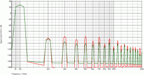
As another exemple below , your own E amp , with the distorsion
of the original schematic and after slight mods to reduce
higher harmonics , i didnt change the compensation for
the purpose and as you can see H2 benefit the less from
the improvements , wich contradict the general idea
that symmetrical circuits favour odd harmonics.
Attachments
I've yet to discover ANY Npn/Pnp Power devices that are true compliments, That's why Quasi/Comp "can" prove superior !
Meanwhile, just put all your sim device characteristics to be the same for npn and pnp to see the cancellation better. Then optimize from there on R values, currents, device c's and strays etc etc.
What is wrong with modifying the models to closely reflect what we have on hand??
Wahab
I don't think you can put plots up like this without talking about the output power and the load. Again, it concerns me when I see harmonics that are flat like that and not declining with frequency.
I don't think you can put plots up like this without talking about the output power and the load. Again, it concerns me when I see harmonics that are flat like that and not declining with frequency.
What is wrong with modifying the models to closely reflect what we have on hand??
Its just to see affect.... what is ultimately possible with that topology. How close you come depends on what we are descussing here.
Another route I like is cancellation techniques.... they keep the parts cost down and can produce some of the lowest distortion anywhere.
It was just brought to my attention another amp with minimal parts but with cancellation... how effective it is. It isnt a CMA but the direction is the same as I have gone with CMA.
I think, once you see the pattern for cancelling, you can do it all over the place. So, for inspiration see Kasey197 at The Valorous Amp... #28 and help him along this direction.
Thx-RNMarsh
- Home
- Amplifiers
- Solid State
- CFA Topology Audio Amplifiers


