I know; It still doesn't explain that with a higher VAS standing current, the slewrate becomes better while not changing the IPS current capability.Its a current, it just flows between two points. As the parasitic capacitances, i look at it as a charge in the input.
Because it lowers the input impedance at low frequencies, making the lowpass filter higher in frequency ?It still doesn't explain that with a higher VAS standing current, the slewrate becomes better while not changing the IPS current capability.
As well as increasing the bandwidth and slew rate, as cascode, in a way, isolate the input from the (non linear) parasitic capacitance of its amplifier transistor ?You might find it interesting to the extent that cascoding will improve CMR as well as PSR. If you have a very low distortion design (under .001% thd), then you dont need to use cascoding to lower the distortion . But you can use it to increase the CM (Common-Mode) Rejection aas well as the PS (Power Supply) Rejection.
Cascode are wonderful.
Last edited:
I know; It still doesn't explain that with a higher VAS standing current, the slewrate becomes better while not changing the IPS current capability.
The ips standing current is generally the limiting factor but depending on your particular circuit there may be others that improve with Vas standing current until you hit the ips limit. Any node with low current and capacitive loading is a candidate to limit slew rate. Hard to say without more details.
jan
An easy way to explore the influence of standing current, separating them from AC impedances, could be the use of a CSS decoupled by capacitances, in the way is working VSSA's input stage ? You can this way change the impedances, without modifying the DC current and vice versa.there may be others that improve with Vas standing current until you hit the ips limit.
That makes sense. In my experience, the IPS itself hardly ever gets pushed into class B/saturation. But in a standard blameless design it's easy for the IPS to 'cut off' the VAS transistor completely while the IPS itself is not anywhere near saturation. So yeah it makes sense considering the IPS itself generally doesn't hit its limits unless severely overdriven by an input signal.Because it lowers the input impedance at low frequencies, making the lowpass filter higher in frequency ?
Well, if the TIS cannot deliver enough feedback current via Cdom, then you are going to have some serious problems. In cases where for example you have the LTP current at say 5mA (2.5 mA per side) and the TIS current is set at say 3mA - and I have seen designs like this on this forum - you will get slew problems because if you drive the input hard, the TIS will not be able to supply enough feedback current via Cdom. If you then correct for this problem by raising the TIS current, you would (erroneously) think that increasing TIS current has increased the slew rate. For this, and other reasons, I usually run my TIS at least 2x ( and often 3x) my LTP current. I wince when I see designs with single digit TIS currents - they are a recipe for problems.
Agreed, I prefer to run the VAS current at 20mA minimally. My MF80 amp which is "only" 80 watts into 4 ohms has a standing current of aproximately 50mA. It has a slewrate capability of ~ 250V/uS.
Going back a bit I've been thinking about square waves, PM and the overall amplifier Q.
In Bob Cordell's book there is a graph of overshoot/frequency response peaking and PM (page 91).
Is this graph related to amplifier Q and how does this relate to group delay? As if you get a consistent group delay you get good square waves but also critical damping should give good square waves.
Apparently, so I read, to get critical damping (ie good sqaure wave output) you end up with a PM of 70 degrees.
Forgive my diversion from the current topic in this thread. Just needed somewhere to dump some thoughts and I seem to remember that amplifier Q was mentioned earlier.
simmed
if this brave preamp sounded good that means that THD is not good tool for estimating of the quality of the amps.
I had to add Miller caps to stabilise it.
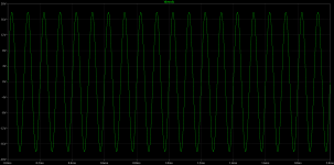
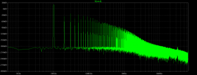
with output voltage as shown had thd ~0.7%
with output voltage 2Vpp thd was ~0.4%
comparing its thd to Dadod's no gnfb thd looks very poor (http://www.diyaudio.com/forums/solid-state/235695-no-nfb-line-amp-gainwire-mk2.html) but I guess that thd is bad thing for comparing the quality of the amps😕
if this brave preamp sounded good that means that THD is not good tool for estimating of the quality of the amps.
I had to add Miller caps to stabilise it.
with output voltage as shown had thd ~0.7%
with output voltage 2Vpp thd was ~0.4%
comparing its thd to Dadod's no gnfb thd looks very poor (http://www.diyaudio.com/forums/solid-state/235695-no-nfb-line-amp-gainwire-mk2.html) but I guess that thd is bad thing for comparing the quality of the amps😕
Attachments

CMA Requires matched compliments -
I wonder why I anticipated that result with a SIM... I said you would have to figure out why a sim doesnt match the measurd test data results. Didnt I?
[ps... put the output zener back to the output and not the emitter. The values of the Re are wrong for that config.]
Its a learning experience. But I gave clues in the characterization of what is needed to have a CMA; Namely, exact matching of transistor characteristics. I used a TEK 576 curve tracer and tested transistor compliments until I found a pair that over-laid each other exactly on the curves. This can now be done, since the 1990's, in IC fab processing. That is when the CMA was able to take-off and become a reality. Find compliments that are exact is needed and a requirement. If not, you will have to rely on gnfb only.
Intuitively, I thought... if a design was symetrical and complimentary and the transistors were exact compliments, distortion would cancel. And, it is true. Thus, very little nfb is needed afterwards.
Thx-RNMarsh
if this brave preamp sounded good that means that THD is not good tool for estimating of the quality of the amps.
I had to add Miller caps to stabilise it.
with output voltage as shown had thd ~0.7%
with output voltage 2Vpp thd was ~0.4%
comparing its thd to Dadod's no gnfb thd looks very poor (http://www.diyaudio.com/forums/solid-state/235695-no-nfb-line-amp-gainwire-mk2.html) but I guess that thd is bad thing for comparing the quality of the amps😕
I wonder why I anticipated that result with a SIM... I said you would have to figure out why a sim doesnt match the measurd test data results. Didnt I?
[ps... put the output zener back to the output and not the emitter. The values of the Re are wrong for that config.]
Its a learning experience. But I gave clues in the characterization of what is needed to have a CMA; Namely, exact matching of transistor characteristics. I used a TEK 576 curve tracer and tested transistor compliments until I found a pair that over-laid each other exactly on the curves. This can now be done, since the 1990's, in IC fab processing. That is when the CMA was able to take-off and become a reality. Find compliments that are exact is needed and a requirement. If not, you will have to rely on gnfb only.
Intuitively, I thought... if a design was symetrical and complimentary and the transistors were exact compliments, distortion would cancel. And, it is true. Thus, very little nfb is needed afterwards.
Thx-RNMarsh
Last edited:
Originally Posted by RNMarsh
Intuitively, I thought... if a design was symetrical and complimentary and the transistors were exact compliments, distortion would cancel. And, it is true.
I've realised the same thing also for years. Most designs are 100% neither though. I've yet to discover ANY Npn/Pnp Power devices that are true compliments, That's why Quasi/Comp "can" prove superior !
I have such a design i worked on with Les Sage of Sage Audio around 25 years ago, & i built. It was never manufactured due to limited funds @ the time. It's quite an unusual circuit. As he died some years ago, i may publish it, possibly on here !
Once pointed out... it is obvious--- To the degree the devices are Not complementary, the distortion will not cancel in a balanced, sysmetrical circuit and distortion will be higher. So, you have to match them by hand for the descrete DIY'er/builder. You'll neeed a characteristic curve tracer. Some deveices are closer than others in being similar. You might find which ones and select from those. I am sure people here have some ideas which transistors they are and can give suggestions. They are going thru the matching for the Marsh headphone amp and have found some very close matches right out of the box -- see #629 for output devices, for example.
Without good matching, you do not get a cancellation and only nfb (VFA) works in that world. Going with the best (for audio) CMA in IC form might be more practicle... certainly more expedient/convenient.
Meanwhile, just put all your sim device characteristics to be the same for npn and pnp to see the cancellation better. Then optimize from there on R values, currents, device c's and strays etc etc.
Thx-RNMarsh
Last edited:
I've often thought that the THAT transistor arrays have some appeal. At least you can get a degree of matching without having to actually match any transistors.
Do you not need a curve tracer to properly match though?
Do you not need a curve tracer to properly match though?
I've often thought that the THAT transistor arrays have some appeal. At least you can get a degree of matching without having to actually match any transistors.
Do you not need a curve tracer to properly match though?
Depends on how low in distortion you want to go. You can get almost unmeasureable levels before any feedback. Throw on some feedback and stablize the parameters and improve others. Impressive numbers while the circuit looks simple. The ckts are simple, in concept, just harder to implement in real life. that is where the true compl proccesses came in and made them useful for practical IC use. For us here in descrete, diy land, its just hand matching. But the results can be impressive. Finding the transistors which do not take a lot of sorting is where the hunt is on to find.
Thx-RNMarsh
Lets put the power supply sensitivity to bed for the time being. You might find it interesting to the extent that cascoding will improve CMR as well as PSR. If you have a very low distortion design (under .001% thd), then you dont need to use cascoding to lower the distortion . But you can use it to increase the CM (Common-Mode) Rejection aas well as the PS (Power Supply) Rejection.
That is what I tried after the 1980 design which ended up looking like this a.t.t. If you try to SIM it and you do not get the 'measured' results i got, then see what you need to correct in the SIM to make it match reality. [I think the outputs were 2N2905A and 2N2219A.]
Thx-RNmarsh
View attachment 366327
RNmarsh,
Interesting schematic!
While I fully agree on the use of the output cascodes, It's a bit more difficult for me to see the use of the input cascodes here.
They seem to "isolate" the collectors of the input transistors from the voltage across the resistor to the supply rail. And this voltage is almost constant and equal to a BJT's Vbe
If possible, a "dynamical" cascode, like on the output (more like a bootstraping cascode) could be very beneficial. It could either be input driven, or driven by the feedback node, whichever is the most convenient (I bet on the later)
Lets try to get back on track here.
So, we've established that the CFA input stage, if correctly biased up, does not transition from class A to class AB or B ( see Richards post #57).
Can we contrast a VFA and a CFA's behavior where the input is driven with an extremely steep rising edge without a front end band limiting filter?
. . .
Bonsai / Richard
Not meaning to be a pest but how do the plots on post #57 establish that a cfa input does not run in class-b?
I agree that for a properly designed stage it should not get close to class b (either cfa or vfa), but again that would indicate that for non overload conditions there is no "slew" advantages.
By class b I am referring to regions which are essentially dominated by the gm one only one Q. If you add dengeneration resistors to the plots on #57 you'll certainly be starving the "off" q when driven by fast edges.
During fast edges of course the cfa input will continue to supply current (within its resitances and current gain) thus essentially eliminating slew (from that stage). If limited by a subsequent stage the input current will still hit roughly the same peak and then decrease as the output gets closer to the target, the slower the stage the longer this will take.
Hope this helps
-Antonio
Going back a bit I've been thinking about square waves, PM and the overall amplifier Q.
In Bob Cordell's book there is a graph of overshoot/frequency response peaking and PM (page 91).
Is this graph related to amplifier Q and how does this relate to group delay? As if you get a consistent group delay you get good square waves but also critical damping should give good square waves.
Apparently, so I read, to get critical damping (ie good sqaure wave output) you end up with a PM of 70 degrees.
Forgive my diversion from the current topic in this thread. Just needed somewhere to dump some thoughts and I seem to remember that amplifier Q was mentioned earlier.
You need a min theoretical phase margin of 75 degrees for that. This results in min overshoot and fastest settling. As a real speaker represents a varying load, ideally you should shoot for slightly higher, around 80 to 85. Its prudent to have a min gain margin of 15 as well. A good side effect youll notice is that THD is lowest around this point.
Paul according to this criteria your amp is right on the ball park.
This is a benefit of the CFA topology, it is randomly and easily achieved.
RNmarsh,
Interesting schematic!
While I fully agree on the use of the output cascodes, It's a bit more difficult for me to see the use of the input cascodes here.
They seem to "isolate" the collectors of the input transistors from the voltage across the resistor to the supply rail. And this voltage is almost constant and equal to a BJT's Vbe
If possible, a "dynamical" cascode, like on the output (more like a bootstraping cascode) could be very beneficial. It could either be input driven, or driven by the feedback node, whichever is the most convenient (I bet on the later)
Indeed, I found a thread some time back where a member Elvee showed sims proving the point.
- Home
- Amplifiers
- Solid State
- CFA Topology Audio Amplifiers