Switching the snubber to the other coil (I also removed a post bridge snubber):

Seems to be making the noise level drop nicely:

Seems to be making the noise level drop nicely:
So in theory... with two snubbers in (removing the residual spikes) the differential noise will be 1.7mVpp with just RCRC filters (-58dBV?), so there's plenty of additional work to be done dropping the noise level using a regulator.

Just looking at options for power regulation.
One option is to make a PCB at a later date. If that's the case I'd probably have three PCBs - one PS/regulator/Caps a left and a right channel board (ie tube + BJT) and possibly some control/input selection. That would allow me to mount LT3080s for example.
However for now I will live with the spikes, once the LV transformer arrives I may need to put a small order for any adjustments of resistors etc, at which point I'll put the order for the snubber resistors.
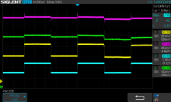
Just tracing some of the signals to track down where the noise is getting in (other than the obvious):
You can see the triode cathode following the mosfet at the bottom, then the BJT base signal:

The top then shows the noise coming in from the other amp without a ground (even grounding the base shows noise).
One thing I love about oscilloscopes is using an probe to detect EMI sources - I can see the line that connects the transformer to the bridge rectifier a massive amount of radiated noise (a good couple of inches). So that looks like it could be redressed closer to the chassis.
That connection and line is close to the the negative rails which obviously puts more EMI to either side of the load.
So take aways the AC/rectification/mains and should be at least 2-4 inches away from any unshielded rails or the amplification components. An option here is to move the rectifiers above the chassis along side the transformers.
You can see the triode cathode following the mosfet at the bottom, then the BJT base signal:
The top then shows the noise coming in from the other amp without a ground (even grounding the base shows noise).
One thing I love about oscilloscopes is using an probe to detect EMI sources - I can see the line that connects the transformer to the bridge rectifier a massive amount of radiated noise (a good couple of inches). So that looks like it could be redressed closer to the chassis.
That connection and line is close to the the negative rails which obviously puts more EMI to either side of the load.
So take aways the AC/rectification/mains and should be at least 2-4 inches away from any unshielded rails or the amplification components. An option here is to move the rectifiers above the chassis along side the transformers.
Attachments

I have enough sheet aluminium plus corner extrusions to make a shielded top box to contain all five transformers (in the end) and AC mains IEC, switches, fuses, rectifiers and power supplies, leaving only the DC to enter into the chassis.
I think the design will be relatively straight forward - AC inlet on one side, then fuses/switches/NTC, then toroids, rectifiers and then finally the DC output on the opposite side of the box. I'll mount the toroids on the box walls so I should have enough space without the centre bolts touching.
The cable dressing will be better and I have the option to put aluminium separators between each stage thus providing further shielding.
Just need to find the time now 🙂
Finally some info.. Mouser has the backordered part in the main catalogue has changed to "Expected 11-Jul-22", so I'm assuming that will ship at that date, then add 5 days from US to UK means it could arrive next week or the week after. That gives me enough time to get get the modifications done and fit the low voltage PS too. I may make a divider below the chassis too given the space will be tight looking at the space taken up by PS.
It has occurred to me that this amp could be made into a class H for driving both headphones and speakers:

I know Broskie did look at different class hybrids and a Class H is not much different to the structure at the moment - only down side is yet another (bigger) power supply. Scaling up could be done using the larger BJTs in parallel.
For my current design, the issue is base drive size. Given the amp is less amplifier more buffer, it may need a darling to pull current for the larger devices.
This then leads onto the Carver style idea of voltage tracking power supplies such as: https://www.semanticscholar.org/pap...Siek/8be0c3300feb414f81a8c30ac2d7ad6558b60dd6
In short substituting the linear supply capable of matching the required input signal voltage for the output device supply thus reducing the power consumption - such as this: https://www.semanticscholar.org/pap...Chen/5c9ca0c19ebf8aee265949c7b197b27829d46398 and built on by this PSRR-focused headphone amp: https://www.semanticscholar.org/pap...Chen/6b69ffdb33d1c050718257089945b866daf4c8a3
In fact a multi-level DSD power DAC would be more effective in this - the DSD driving the voltage for the power supply but there's no need with a simple DSD driving the switching of the power supply itself. Which could be done for both tube and tube-hybrid HPAs.
However I digress and for now this is not the main priority at the moment 🙂
Last edited:
Whilst I wait I'm now starting to ponder ideas for the output mute and safety. Looking at the failure modes:
Open tube
This creates a zero voltage on the local BJT cutting it off and thus causing the channel to operate as a single ended amp.
Cathode to Anode B+ shorted tube
The important point is that the headphones are connected to ground at 1K either side. Thus a tube failure sees 1K in parallel with a 55R+1K load given the opposing amp will not match the signal. The result is that the 1K||(55R+1K) = 49.5R (let's just say 49R).
This creates a resistance of Ra (1.1K)+500R+12R (Ron)+10R+68R+49R = 1739R with 180V which = 103mA. The BJT sees 0.103*65R = 6.7 Vbe. The maximum is 7.0Vbe. At 1.0Vbe the BJT would be Von and passing full current (max continuous 4A peak 8A with 100Vds). So perhaps a voltage clamp of <1.0Vbe would be useful in this context to protect the low voltage power supply and BJT.
The P channel VP2106 mosfet will see a Vds increase to 1.1K*103mA-(578+49R)*103mA= 58.8Vds across it. The max Vds is 60V. The Vs would then rise to (578+49)*103mA = ~65Vdc. The Vgs diode would only conduct <1mA thus the Vgs would be ~65V and the 1.78M resistor in the LPF needs to be rated to cope (IIRC mine is 200V).
This will destroy the gate thus cannot be guaranteed to prevent it shorting (removing 12R from the resistance chain) or failing open which cuts current flow for the tube. The only way to protect this is to voltage clamp across the Vds to ensure that the Vgs doesn't exceed the max 20Vgs rating!
So the maximum current we should allow before tripping is 3.0/(578+49) = 4.7mA which won't work for our tube. Grrr. So the best option is to accept the SOA failure mode of the VP2106 for now but limit the current to 25mA with a fuse.
Now this doesn't include current draw through the headphones.
This leaves the headphones with one amp operating with approximately 55R||1K = 52R * 103mA = ~5.4Vdc (not including the peak on the opposite side. This means the opposing p-channel mosfet could see >3.0Vgs leading to opposing mosfet gate failure.
So a good thing would be a 2V differential voltage trigger (the headphones are 104dB/V sensitivity) to trigger a controlled B+ short and blow the fuse.
Cathode to Heater short
We're using 12.6Vdc heaters, so lets say the heater supply was grounded on one side and use 13Vdc heater shorted to the cathode. The heater supply is capable of providing 2.5A at 12.6Vdc.
Initially the 13V instead of 5V would raise the current a maximum if 13/(12+500+10+68+49) = ~20mA which is well within the SOA. The Vgs would rise to 12.6V resulting in Ron and a Vds of 0.24Vds which would shut down the mosfet, oscillating until an equilibrium is found or SOA current results in a dead mosfet.
The increase in Vbe > 1.0V would resulting in the parallel BJT turning on fully thus a large current would be drawn through the headphones.
The use of a 1A fuse slow blow heater rail fuse would be required to cope with heater startup. The use of a fast blow 250mA fuse for the low voltage power supply would help however this would cause the B+ sat on top to simply drop in voltage but the heater supply is still pulling through the the headphones. The heater being a 300R to ground in parallel with a 49R to ground, the current without the BJT would be 310mA would flow through the headphones.
I'm currently modelling this failure mode in LT spice - my calculation is almost correct:

The option for controlling this is an over volt sense (or a current sense using the 10R resistor) to disconnect all the power supplies by a enabling all the crowbars and thus blowing all the fuses. An alternative is having power disconnect relay with a dropping latch allowing a big red warning light to show..
BJT open
Channel becomes unbalanced
BJT short
A shorted BJT results in a 49 ohm load across the LV power supply. Kiss goodbye to the headphones so a quick blow fuse and a current limiting regulator is likely to be a good addition on the LV supply.
Headphone short
A shorted headphone will impact both BJT and essentially results in large currents .. again current regulation required.
So there's a couple of common themes that could made but a current limiting voltage regulator on each power supplies seems a good start.
- open tube
- Cathode to Anode B+ shorted tube
- Cathode to H shorted tube
- Higher Bias failure (high current)
- BJT open
- BJT short
- Differential DC voltage failure
Open tube
This creates a zero voltage on the local BJT cutting it off and thus causing the channel to operate as a single ended amp.
Cathode to Anode B+ shorted tube
The important point is that the headphones are connected to ground at 1K either side. Thus a tube failure sees 1K in parallel with a 55R+1K load given the opposing amp will not match the signal. The result is that the 1K||(55R+1K) = 49.5R (let's just say 49R).
This creates a resistance of Ra (1.1K)+500R+12R (Ron)+10R+68R+49R = 1739R with 180V which = 103mA. The BJT sees 0.103*65R = 6.7 Vbe. The maximum is 7.0Vbe. At 1.0Vbe the BJT would be Von and passing full current (max continuous 4A peak 8A with 100Vds). So perhaps a voltage clamp of <1.0Vbe would be useful in this context to protect the low voltage power supply and BJT.
The P channel VP2106 mosfet will see a Vds increase to 1.1K*103mA-(578+49R)*103mA= 58.8Vds across it. The max Vds is 60V. The Vs would then rise to (578+49)*103mA = ~65Vdc. The Vgs diode would only conduct <1mA thus the Vgs would be ~65V and the 1.78M resistor in the LPF needs to be rated to cope (IIRC mine is 200V).
This will destroy the gate thus cannot be guaranteed to prevent it shorting (removing 12R from the resistance chain) or failing open which cuts current flow for the tube. The only way to protect this is to voltage clamp across the Vds to ensure that the Vgs doesn't exceed the max 20Vgs rating!
So the maximum current we should allow before tripping is 3.0/(578+49) = 4.7mA which won't work for our tube. Grrr. So the best option is to accept the SOA failure mode of the VP2106 for now but limit the current to 25mA with a fuse.
Now this doesn't include current draw through the headphones.
This leaves the headphones with one amp operating with approximately 55R||1K = 52R * 103mA = ~5.4Vdc (not including the peak on the opposite side. This means the opposing p-channel mosfet could see >3.0Vgs leading to opposing mosfet gate failure.
So a good thing would be a 2V differential voltage trigger (the headphones are 104dB/V sensitivity) to trigger a controlled B+ short and blow the fuse.
Cathode to Heater short
We're using 12.6Vdc heaters, so lets say the heater supply was grounded on one side and use 13Vdc heater shorted to the cathode. The heater supply is capable of providing 2.5A at 12.6Vdc.
Initially the 13V instead of 5V would raise the current a maximum if 13/(12+500+10+68+49) = ~20mA which is well within the SOA. The Vgs would rise to 12.6V resulting in Ron and a Vds of 0.24Vds which would shut down the mosfet, oscillating until an equilibrium is found or SOA current results in a dead mosfet.
The increase in Vbe > 1.0V would resulting in the parallel BJT turning on fully thus a large current would be drawn through the headphones.
The use of a 1A fuse slow blow heater rail fuse would be required to cope with heater startup. The use of a fast blow 250mA fuse for the low voltage power supply would help however this would cause the B+ sat on top to simply drop in voltage but the heater supply is still pulling through the the headphones. The heater being a 300R to ground in parallel with a 49R to ground, the current without the BJT would be 310mA would flow through the headphones.
I'm currently modelling this failure mode in LT spice - my calculation is almost correct:
The option for controlling this is an over volt sense (or a current sense using the 10R resistor) to disconnect all the power supplies by a enabling all the crowbars and thus blowing all the fuses. An alternative is having power disconnect relay with a dropping latch allowing a big red warning light to show..
BJT open
Channel becomes unbalanced
BJT short
A shorted BJT results in a 49 ohm load across the LV power supply. Kiss goodbye to the headphones so a quick blow fuse and a current limiting regulator is likely to be a good addition on the LV supply.
Headphone short
A shorted headphone will impact both BJT and essentially results in large currents .. again current regulation required.
So there's a couple of common themes that could made but a current limiting voltage regulator on each power supplies seems a good start.
So hacked and riveted some recycled alu:

The layout I'm thinking - this allows five transformers but will need some insulation between the centre pins of the toroids.

So this will hold AC Line filter, primary fuses, NTC, switches, transformers and rectifiers. This leaves a short amount of cable between rectifiers to PS to enter into the lower chassis but they will be well away from the signal and rails unlike before.
Naturally each chassis panel will have it's own binding to ground along with the ground star.
Already hot in the garage - it was 37degC in the sun yesterday, so I suspect it will get over 40degC this week.
The layout I'm thinking - this allows five transformers but will need some insulation between the centre pins of the toroids.
So this will hold AC Line filter, primary fuses, NTC, switches, transformers and rectifiers. This leaves a short amount of cable between rectifiers to PS to enter into the lower chassis but they will be well away from the signal and rails unlike before.
Naturally each chassis panel will have it's own binding to ground along with the ground star.
Already hot in the garage - it was 37degC in the sun yesterday, so I suspect it will get over 40degC this week.
I'm nowhere near knowledgeable enough to make comments of the electronics of this, but I have been fascinated by the process and wanted to say thanks for taking the time and trouble to write this level of detail. My background is programming and I know you have plenty of expertise in that area too. It's been interesting to see the parallels between electronic and software development.
Also the way to understand it is no different - experiment. Set yourself a simple starting point then implement it.
There are patterns and architectures - each with their pros and cons.
There are patterns and architectures - each with their pros and cons.
Your order has shipped.
It has a scheduled delivery date of Friday 🎉 and it seems to be shipping priority too.
Just thinking a little on the safety points above for the final 9 power supplies.
I like the concept of a trip line. Each PS output is governed by a 5V enable output or <4.5V disable output. All the power supplies outputs are connected to the trip line and should one supply have a problem and ground the trip line then all output power is cut. A latch on the trip prevents the line from being re-enabled.
The trip line itself can be tripped by over current sensing or over voltage sensing without being worried about the floating arrangement of the PS. That could be via isolation opto couplers if the response time is good enough.
If I'm messing with the supply outputs then adding current limiting voltage regulator can be made to work with the trip and switchable output. I may be inclined to place them on a PCB to reduce the size. I can order a batch of 10 PCBs and have one spare.
Startup could be as simple as press on with a delay for the heaters or more complex in waiting until the voltage for each PS reaches the correct level before enabling output.
For now let's get the channel working 🙂
Well it's finally arrived. Just trying a dry fit in the new upper chassis, you can spot the difference between the 120VA (HT and heaters) and the 80VA (LV):

It doesn't matter which, Hammond supply the same length bolt with them which means the 120VAs don't have much room with the thickness of the aluminium! 80VA fairs better with the slimmer core. The Red insulating tape is to protect the insulation on the toroids given the rubber only covers 1/2 the underside of the toroid. I don't want anything damaging the insulation and it offers some grip against the aluminium
So this afternoon's tasks:
1. Cut/drill any final bits for the pictured power chassis, fit the IEC/NTC/switches/Fuses and earth bonding and cable blocks for the transformers.
2. Drill/punch grommet holes for the lower chassis.
3. Fit the HV, LV and heater PS RCRC filters in the right spots in the main chassis then wire up.
4. Test each PS again
5. Test Tube side.
6. Fit the BJTs and SMT caps to the HS
7. BOOM, err I mean test the BJTs now for the fully operational Death Star/Trap.
8. Scope up and check how it's getting on.
Note for now I will not have the 1.8R+cap snubbers running on the amp. I figured I'd wait until have any adjustments to make then combine the orders.
I may not get all the above done today but I'll give some photos of progress.
Done for today. I'm not going to rush and there's beer, snacks and pizza downstairs for film night.
It's surprising how long it takes to make earth bonding links between the panels - crimped and soldered. However the power is is complete up to the connector blocks for the transformer primaries. They have to be staggered due to the primary lead reach on the 80VA being shorter. Each primary set will also connect up the CT at these posts too. The circuit is the same as before and the MOV will sit on the primary connection side,

I've also manage to somehow misplace my chassis punch and wasted time today searching - 21mm is perfect for the grummets not just the tubes.
It's surprising how long it takes to make earth bonding links between the panels - crimped and soldered. However the power is is complete up to the connector blocks for the transformer primaries. They have to be staggered due to the primary lead reach on the 80VA being shorter. Each primary set will also connect up the CT at these posts too. The circuit is the same as before and the MOV will sit on the primary connection side,
I've also manage to somehow misplace my chassis punch and wasted time today searching - 21mm is perfect for the grummets not just the tubes.
After testing PE to each of the alu panels in the new piece it was time to power up the set of transformers - the new 80VA hums quite loudly vs the both 120VA transformers being entirely silent. I'll investigate later if there's too much AC noise causing it's primary a problem or if it simply a crap laminated toroid core given it's new backorder from Hammond. I suspect it's the latter and Hammond have being using other vendors for their cores? Not happy with Hammond.
New 22V unloaded gives 25.xV so next steps are setting up the rectifiers and hooking up the power supply. Maybe the larger 120VA cores aren't as easily saturated by any DC on the main AC.
New 22V unloaded gives 25.xV so next steps are setting up the rectifiers and hooking up the power supply. Maybe the larger 120VA cores aren't as easily saturated by any DC on the main AC.
So a initial all PSU test startup with NTC engaged and the HV switched on at start for full inrush. All good - no blown fuses but I will add the MOVs on the primary side.
PSU Volts unloaded:
Heater = 16Vdc
HV = 175Vdc
LV = 32Vdc
I'm happy I did a bleed resistor and a LED. It makes experimental rebuilding easier.
So happy with that progress. Now I need to find my chassis punch and then I can crack on - very annoying .
.

PSU Volts unloaded:
Heater = 16Vdc
HV = 175Vdc
LV = 32Vdc
I'm happy I did a bleed resistor and a LED. It makes experimental rebuilding easier.
So happy with that progress. Now I need to find my chassis punch and then I can crack on - very annoying
.If I can't find things after misplacing them, the only way forward is to buy them again. The misplaced thing will then re-appear automagically. 🙄Now I need to find my chassis punch and then I can crack on - very annoying
- Home
- Amplifiers
- Headphone Systems
- C'est Compliqué - Broskie Hybrid Tube Circlotron