Had a bit of a brain barf about the switches - of course they're ok, they're on the AC side of the transformers!
AC powered neons (not sure on the noise impact) but these aren't as bright as the image would have you believe:

Next step is to hook up the transformers, BR and the power supplies for the next step. Then it's tube time as I wait for the LV transformer.
That will do for tonight. I'm tired and I won't continue AC/HV work when tired.
AC powered neons (not sure on the noise impact) but these aren't as bright as the image would have you believe:
Next step is to hook up the transformers, BR and the power supplies for the next step. Then it's tube time as I wait for the LV transformer.
That will do for tonight. I'm tired and I won't continue AC/HV work when tired.

I've just been drawing out a channel point-to-point configuration, it's not ideal but will work. The signal paths are elevated from the heater and HV/LV supply wires.

It's also occurred to me I may want to add a reverse polarity diode on the HV power supplies for power down scenarios to prevent the scenario when the HV supply bleeds faster than the LV power supply and heater supply. Although the tube won't conduct without HV I want the supply protected.
It's also occurred to me I may want to add a reverse polarity diode on the HV power supplies for power down scenarios to prevent the scenario when the HV supply bleeds faster than the LV power supply and heater supply. Although the tube won't conduct without HV I want the supply protected.
So I've been thinking this morning about inrush and voltage surges when the parallel toroids are switched off. In the individual PS testing for the HV toroid there was a distinct 'click' through headphones of a separate electrical device.
I've ordered a few things - a 55R 5W load resistor 😀 Some MOVs for incoming voltage spikes but also for switching off the inductive load of a toroid. A reasonably large NTC which I may put with a manual shorting switch for now. I may not need this but I was ordering anyway. A polarity protection diode for each PS. They had some MURS840s for 0.12 each.. Some caps the 1957 receiver that I forgot previously and a to reduce the small order handling charge, a cheap silvertronic 1000V multimeter lead kit with crocs, clipo-ns etc to allow me to connect up and not have my fingers inside with spike probes.
I hope to have the majority of the amp done this weekend - then just slot the LV power toroid in when it finally arrives.
So I've trial fitted the transformers in the position I had envisaged:

However I'm concerned (for now) the stress being put on the wires - I think for now I will simply put the transformers on the other side until I work out a better way. It will stop the strain and also protect the transformers as they're not potted.
My death-trap wiring so far:

IEC filter (switched+fused) + MOV across L+N -> NTC [left switch bypasses] -> fuses
IEC filter earth -> chassis with bolt and shake proof washer + second to act as ground.
fuse -> right switch -> transformer primary, HV secondaries (2x) -> bridge rectifier (2x) -> power supplies (2x)
fuse -> heater transformer primary, heater secondaries (2 in parallel) -> bridge rectifier (1x) -> power supply (1x)
fuse -> transformer (missing) -> transformer primary, LV secondaries (2x) -> bridge rectifier (2x) -> power supplies (2x)
I will fit three MOVS across the each of the transformer primaries.
This is going to be heavy.. very heavy lol.
However I'm concerned (for now) the stress being put on the wires - I think for now I will simply put the transformers on the other side until I work out a better way. It will stop the strain and also protect the transformers as they're not potted.
My death-trap wiring so far:
IEC filter (switched+fused) + MOV across L+N -> NTC [left switch bypasses] -> fuses
IEC filter earth -> chassis with bolt and shake proof washer + second to act as ground.
fuse -> right switch -> transformer primary, HV secondaries (2x) -> bridge rectifier (2x) -> power supplies (2x)
fuse -> heater transformer primary, heater secondaries (2 in parallel) -> bridge rectifier (1x) -> power supply (1x)
fuse -> transformer (missing) -> transformer primary, LV secondaries (2x) -> bridge rectifier (2x) -> power supplies (2x)
I will fit three MOVS across the each of the transformer primaries.
This is going to be heavy.. very heavy lol.
First power on was with just the heater filter and all the transformers & rectifiers connected - the idea was to check my wiring before adding caps. This is not the final wiring configuration.
I blew one 1A fuse on power off initially - the HV transformer didn't have a load and the back emf crossed the MOV after IEC filter causing current across that fuse. Each transformer primary has a MOV across it to limit the spike - this has worked well since.
The unloaded HV filter gives ~175Vdc.

The unloaded heater supply gives 16Vdc currently so this needs some attention. I did put both secondaries of the transformer rather than a single so that could be boosting the voltage.

You can see the LEDs indicating the charge on the capacitors.
Later today I will break out the scope and see what the ripple is.
I blew one 1A fuse on power off initially - the HV transformer didn't have a load and the back emf crossed the MOV after IEC filter causing current across that fuse. Each transformer primary has a MOV across it to limit the spike - this has worked well since.
The unloaded HV filter gives ~175Vdc.
The unloaded heater supply gives 16Vdc currently so this needs some attention. I did put both secondaries of the transformer rather than a single so that could be boosting the voltage.
You can see the LEDs indicating the charge on the capacitors.
Later today I will break out the scope and see what the ripple is.
So I've stuck the scope on and I have the first ripple figures.
Each HV PS is 175Vdc unloaded 240mVpp.
The heater PS is 16Vdc unloaded 34mVpp.
I then changed the probing. Using channel 1 & 3 to get 1GSPS, I grounded the floating supplies and measured the difference between the two:

So the residual ripple residing is about 35-42mVpp for the HV supply. dBmV = 20log10 (level in millivolts/1 millivolt) => 20log10(24) = -27mdBV, then converting from mdBV to dBV is -60 to that so -87dBV.
This doesn't include the 1u film cap which I will try now - edit: the HV supply now measures 206-216mVpp so next up trying both with the 1uF cap across it.
Each HV PS is 175Vdc unloaded 240mVpp.
The heater PS is 16Vdc unloaded 34mVpp.
I then changed the probing. Using channel 1 & 3 to get 1GSPS, I grounded the floating supplies and measured the difference between the two:
So the residual ripple residing is about 35-42mVpp for the HV supply. dBmV = 20log10 (level in millivolts/1 millivolt) => 20log10(24) = -27mdBV, then converting from mdBV to dBV is -60 to that so -87dBV.
This doesn't include the 1u film cap which I will try now - edit: the HV supply now measures 206-216mVpp so next up trying both with the 1uF cap across it.
Last edited:
So the 1uF seems to calm the difference slightly but overall there's still ripple. -90dbV or so.
Last edited:
So I'm looking at the layout - this is the current schematic:

The wiring draft:

Notes:
a) Tube triode bias adjustment - this is assuming a matched tube triode, I can add a variable resistor to vary the bias.
b) The VP2106 performs DC based bias adjustment.
c) MJE243 heat variation - there's no varistor heat bias adjustment.
The wiring draft:
Notes:
a) Tube triode bias adjustment - this is assuming a matched tube triode, I can add a variable resistor to vary the bias.
b) The VP2106 performs DC based bias adjustment.
c) MJE243 heat variation - there's no varistor heat bias adjustment.
A long day.

I will order the required 13.4R for dropping the tube supply from 16.64V to 12.6V. Other than that - noted that Mouser shipped a 5K6 resistor (marked and measured) instead of the 55K that I ordered. Seems they have a problem there! I'm still waiting on a backorder update for the LV toroid.
Next steps:
1. Heater supply voltage sorted. I was going to run a 1M divider to ground but instead I can simply tie the negative instead.
2. Heater only power up with a tube.
3. HV power up without a tube present and current limited.
When the LV transformer arrives I'll install the BJTs but for now I can test enough with just the tubes.
Actually it occurred to me that my load resistors are 100W 8R in series gives me 16R, measured at 16.8 with two 1K 3W in parallel will drop to 11.735V which is within the 12.6V ±1V of the 12BH7A-STRs. So I can try that initially to power the heater.
It also occurred to me that I had put 4 tube heaters in parallel rather than one per pair of triodes hence the error in calculation. Not a biggie as it provides headspace for relegation/more load at a later date. The parallel transformer secondaries also halves the impedance so provides more current too.
It also occurred to me that I had put 4 tube heaters in parallel rather than one per pair of triodes hence the error in calculation. Not a biggie as it provides headspace for relegation/more load at a later date. The parallel transformer secondaries also halves the impedance so provides more current too.
I made a minor boo-boo, the VP2106 p-ch mosfet has a -3.5VgsMax. The simulation shows around 9V max gate and <1V source. So that's not going to work. So for now I will remove the mosfets, test the amp and see the true characteristics then look for a more suitable mosfet. That will teach me to use the search in mouser -20V/+20V rather than the datasheet.
The joys of 'designing' your own amp. I think it's about time to put the LTSpice model to one side as theory moves to applied prototyping 😀
The joys of 'designing' your own amp. I think it's about time to put the LTSpice model to one side as theory moves to applied prototyping 😀
Last edited:
Edit: https://www.mouser.co.uk/datasheet/...Enhancement_Mode_Vertical_DMOS_FE-2887725.pdf shows VgsMax as ±20V compared to the (I assume non-G) at -3.5V.. ok back to test it and see if it goes pop.
A beautiful thing:

Note - the phone used night time timed photo so the tube is appearing redder than it is.
I have a 10R resistor cathode side which works nicely to show the current through the tube, this is 8.5mA on each of the triodes which is probably a little low as the heaters are a little low with the 16R I added. I had planned around 9mA idle.

This has been running for 5-10 minutes and no issues of red plating etc. This also has the mosfet in place after this morning's brain barf.
Later today I will get the scope out and also test the voltage drops of the HV power supply.
Note - the phone used night time timed photo so the tube is appearing redder than it is.
I have a 10R resistor cathode side which works nicely to show the current through the tube, this is 8.5mA on each of the triodes which is probably a little low as the heaters are a little low with the 16R I added. I had planned around 9mA idle.
This has been running for 5-10 minutes and no issues of red plating etc. This also has the mosfet in place after this morning's brain barf.
Later today I will get the scope out and also test the voltage drops of the HV power supply.
First - I don't have the 1uF caps on the power supplies nor the 0.22uFs across the bridge rectifiers.
Let's simply try a single phase - you can see the diode switching noise 😱

However this is a circlotron - how much noise do you have if you subtract either side? CH1 and CH3 on opposite sides of the resistor.

Err the oscilloscope can't measure it - the inputs traces are 200mV/div but the maths is at 5mV/div... nothing.. nada.. zip. 😎
Let's simply try a single phase - you can see the diode switching noise 😱
However this is a circlotron - how much noise do you have if you subtract either side? CH1 and CH3 on opposite sides of the resistor.
Err the oscilloscope can't measure it - the inputs traces are 200mV/div but the maths is at 5mV/div... nothing.. nada.. zip. 😎
Now that's when your scope decides to switch the channels back. 🤦 in reality it's this:

So using the cursors to ignore the switching noise from the bridges, the noise is now 48mV. Perhaps my calculation is bad but -108dBV. Annoyingly I can't FFT the difference between two channels.
So using the cursors to ignore the switching noise from the bridges, the noise is now 48mV. Perhaps my calculation is bad but -108dBV. Annoyingly I can't FFT the difference between two channels.
Way to early todo this but as the scope is hooked up:

So this is single ended without terminating the other input to ground:
a) the mains noise shows that the bridges need snubbers as it's causing the spikes
b) the amp is giving a reasonably flat response through to 20KHz.
c) -45db is low, not surprising considering this is a cathode following input without the BJT adding the required current.
So if I could differential the FFT then the diode spike + harmonics would be less.
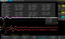
So this is the beastie that's causing all the noise:

At 50/100Hz and 1.02V, that's quite a bit of ringing and matches the Rectron BR104 400V 10A bridges I'm currently using. So I think from that a snubber could be made.
At 50/100Hz and 1.02V, that's quite a bit of ringing and matches the Rectron BR104 400V 10A bridges I'm currently using. So I think from that a snubber could be made.
Update - after adding the 1uF caps into the power supplies, redressing the wires a bit - I've improved the general noise floor but next step is targeting the diode-transformer spikes.
First the general output from a single amp:

Next this is the difference at the load - only 16.8mV of non-diode spike noise (20log10(16.8m)=-35 then -60 for -95dBV):

This creates a spray of FFT harmonics on each amp:

First the general output from a single amp:
Next this is the difference at the load - only 16.8mV of non-diode spike noise (20log10(16.8m)=-35 then -60 for -95dBV):
This creates a spray of FFT harmonics on each amp:
Attachments
Last edited:
So first attempt to reduce the spike with one of the 117V secondaries with a 2200pF 1.2kV FKP1 cap and a 1K + 10K variable resistor (5W 500V rated):
1K only

1K+some variable resistor:

Next step is to increase from 2200pF to a larger 220nF FKP1 600V and retest.
1K only
1K+some variable resistor:
Next step is to increase from 2200pF to a larger 220nF FKP1 600V and retest.
With a 220nF X2 class + 1K + variable resistor:
Variable to zero:

Going...

Going..


This seems to be the sweet spot with the 220nF (note the scale):

The FFT also seems to be improving:

The other opposing amp still has no snubber so it shows up hence the FFT noise.

Measured the resistor + variable resistor = 1.8R
Variable to zero:
Going...
Going..
This seems to be the sweet spot with the 220nF (note the scale):
The FFT also seems to be improving:
The other opposing amp still has no snubber so it shows up hence the FFT noise.
Measured the resistor + variable resistor = 1.8R
Last edited:
- Home
- Amplifiers
- Headphone Systems
- C'est Compliqué - Broskie Hybrid Tube Circlotron