@billshurv,
Every track is played back flawlessly.
Never saw a stylus at any price point that produced a "flawless" signal. Show me a 1/3 octave noise band @5kHz with no IM distortion. Forgot about your tonearm thread, has anyone else experimented with it. I wish I had the time.
Last edited:
@scott wurcer,
You are 100% right!!! ;-))
The test record – Hifinews – has a description upon the cover “how to determine the results”. “Flawlesly” is only in relation to these “standards”.
Brasnwood (member of DIYaudio) has made 2 tonearms. His opinion doesn't differ from my experience. Neverthelsess, 2 days ago I have ordered single wire enameled "magnet" copperwire (0.06 mm). Its just single Litz wire (Ebay).
The resistance against deforming of single wires is less than a couple of wires that has been twisted. So the tonearm has to operate in an easier way. Besides that, the electrical resistance of 90 cm Litz wire (20 x 0,05 mm) is 0,45 ohm. I have a low output MC cartridge, so 20 x 0,06 mm will result in 0,3 ohm (less noise).
@sreten,
I cannot find the word "variable" in your original post (#50). Maybe you can post a drawing that shows your idea?
There is one more problem: you cannot exchange the modification of the records by the modification of the turntable. So your solution has to work well without a new spindle/platter bearing.
Hi,
The variablity is implicit in the construction.
"Think of two circles above each other but
joined via a pin that is a little off centre,"
Intially they are concentric, rotating the top
relative to the bottom its variably eccentric,
with a maximum at 180 degrees rotation.
Top down view of the spindle.
It should obvious from the details of the original post.
I'm still getting NIHS, refusal to join the dots.
I certainly can exchange some work on the deck for
no physical modifications of the records if I want.
(Other than the two label periphery marks.)
Still no excuse not to understand the suggestion.
Yes it would need some skillful engineering,
but it does the job, and would work if built.
rgds, sreten.
Last edited:
Intially they are concentric, rotating the top
relative to the bottom its variably eccentric,
with a maximum at 180 degrees rotation.
Top down view of the spindle.
rgds, sreten.
That is a neater solution than the 2 I came up with today. My option 1 was tape across the hole to align with my inner (2mm) spindle. Option 2 was a wedge with an offset hole that could be slid up and down the inner spindle. I have an advantage of a void under the record label.
Bill
Neverthelsess, 2 days ago I have ordered single wire enameled "magnet" copperwire (0.06 mm). Its just single Litz wire (Ebay).
The resistance against deforming of single wires is less than a couple of wires that has been twisted. So the tonearm has to operate in an easier way. Besides that, the electrical resistance of 90 cm Litz wire (20 x 0,05 mm) is 0,45 ohm. I have a low output MC cartridge, so 20 x 0,06 mm will result in 0,3 ohm (less noise).
Enameled copper wire (or ECW) is not litz wire? some forms of litz are made from ECW, but many are not. Not quite sure how this is pertenant.
@scott wurcer,
You are 100% right!!! ;-))
The test record – Hifinews – has a description upon the cover “how to determine the results”. “Flawlesly” is only in relation to these “standards”.
What vintage is your test record? Mine is 1996 issue and I have just pulled it out and it has no mention of 'flawlessly' on the cover?
I am still worried that you measure no resonance on the LF sweeps, as this suggests you have a resonance much higher up, which is not good.
They all have high end turntables with drive belts and very heavy platters.
Three solutions:
1. Using the laser stylus gadget and an optical system, characterize the in/out movement of the tonearm.. Then, using a cnc machine, machine away the platter surface where the belt contacts it. To retain balance, a second groove has to be machined 180 degrees out.
2. Using the laser stylus gadget, servo the tonearm base on a curved rail. When the groove is furthest from the hole, move the tonearm in the same direction as platter rotation, and when closest, move the tonearm opposite.
3. Mount the entire turntable and tonearm assembly on a larger rotatable platform. Rotate the platform instead of the tonearm.
jn
Sample with a modulated clock. Replay with an unmodulated clock. Maybe you could read the head position with a laser and use that to modulate the clock, or perhaps that's over-fussy? You could sync to it for sure.
Really guys listen to your LP's, enjoy, end of story. Seriously all those folks with Goldmund References and Koetsus in the 80's were hearing s**t.
Spoilsport. I am still trying to work out how to mount a laser on my tonarm. Dr Evil would be proud of a tonearm with a frikkin laser on it. Easier to care for than a shark as well.
@ALL,
(There are a lot of questions, sorry I will answer them tomorrow.)
An easy solution... Look to the image below.
The size is 38,1 mm (extended centre hole of a 7 inch single). The height about 10 mm (just like the well known adaptor).
When we have centred a record, we mark the position of the yellow pointer on the label of the record. And... we write upon a sticker at the label the position of the black pointer. For example 30 (image), or 54, etc. It is just like the minutes of a clock.
Now we want to hear the music... We look upon the sticker and read the value. Next we turn the pointer of the outer ring at the right position. So we only have to align the marker at the label of the record with the yellow pointer of the inner ring before we put the record around the new spindle. That’s all. Not the time consuming centering of the Nakamichi Dragon but a real fast adjustment of the right correction of the eccentricity (2 or 3 seconds).
Drilling perfect centre holes is possible with a 38 mm centre fraise (see image below).
I only have to replace the drill inside with a bar/rod that’s 7,2 mm wide (and it must be perfect centred otherwise the centre hole will become too large.
(There are a lot of questions, sorry I will answer them tomorrow.)
An easy solution... Look to the image below.
An externally hosted image should be here but it was not working when we last tested it.
The size is 38,1 mm (extended centre hole of a 7 inch single). The height about 10 mm (just like the well known adaptor).
When we have centred a record, we mark the position of the yellow pointer on the label of the record. And... we write upon a sticker at the label the position of the black pointer. For example 30 (image), or 54, etc. It is just like the minutes of a clock.
Now we want to hear the music... We look upon the sticker and read the value. Next we turn the pointer of the outer ring at the right position. So we only have to align the marker at the label of the record with the yellow pointer of the inner ring before we put the record around the new spindle. That’s all. Not the time consuming centering of the Nakamichi Dragon but a real fast adjustment of the right correction of the eccentricity (2 or 3 seconds).
Drilling perfect centre holes is possible with a 38 mm centre fraise (see image below).
An externally hosted image should be here but it was not working when we last tested it.
I only have to replace the drill inside with a bar/rod that’s 7,2 mm wide (and it must be perfect centred otherwise the centre hole will become too large.
Last edited:
Spoilsport. I am still trying to work out how to mount a laser on my tonarm. Dr Evil would be proud of a tonearm with a frikkin laser on it. Easier to care for than a shark as well.
I am purchasing a new keyboard. Thank you, I needed to spew coffee on the old one.
Best laugh I've had in months.
jn
@billshurv,
(#86) Enameled copper wire is used in Litz wire. A well known manufacturer of Litz wire and single enamelled copper wire is Elektrisola (Germany).
(#87) Test record from autumn 2013. There are no LF resonances. First, it is not a fixed pivot tonearm (no offset angle). Second, the tonearm is excellent damped by the water in the bowl.
(#91) Don’t use your tonearm for the laser. Get an old one and mount an old cartridge under the headshell. Fix the stylus/cantilever with glue, because it must be a total rigid construction between the tip of the stylus and the tonearm bearing.
You can fasten the laser pen firmly with tape. The right position (in line with the stylus) isn’t so important. Even when you attach the laser pen at right angles from the armtube, you see the red dot moving to and fro at the wall when you rotate the record.
@oshifis (#80),
There are a lot of mechanical reasons to enlarge the diameter of the centre hole (for example, increasing the surface area to avoid wear). Besides that, I don’t see any problems when I increase the diameter of the centre hole (post #92).
@jneutron (#88),
Everybody likes it to keep it simple and cheap (DIY).
@sreten (#84),
If I understand your description well, your idea is just 2 non-concentric rings. But not in the horizontal plane but in the vertical plane.
Fix the stylus/cantilever with glue, because it must be a total rigid construction between the tip of the stylus and the tonearm bearing.
Tom, I suspect this will destroy the test record.
After thinking about it, it would be easier to build a flutter meter. A simple hi-Q filter at 3.15 kHz with diode limiter could be made with a 50 cent op-amp. Then this goes into a cheap CMOS PLL chip with a simple oscillator as reference. The control voltage on the PLL is the instantaneous frequency.
The filtering and limiting could also be done with free software (like SoX) in real time.
Now you just tune out the FM till it's just the noise floor.
(#91) Don’t use your tonearm for the laser. Get an old one and mount an old cartridge under the headshell. Fix the stylus/cantilever with glue, because it must be a total rigid construction between the tip of the stylus and the tonearm bearing.
You can fasten the laser pen firmly with tape. The right position (in line with the stylus) isn’t so important. Even when you attach the laser pen at right angles from the armtube, you see the red dot moving to and fro at the wall when you rotate the record.
Just polish a surface of the tonearm mount as a reflector. Doubles the sensitivity.
Where's the fun in that???@jneutron (#88),
Everybody likes it to keep it simple and cheap (DIY).
No, more complex is better. Ridiculously complex, far better.
Rube Goldberg complex: audiophile heaven.
Why do something with only one part when a thousand can do it almost as well??
jn
ps. On second thought, how about an optical encoder on the tonearm pivot. Back of envelop calc: 1 mil 1 inch out is 1 milliradian, 100 mils 10 inches out is 10 milliradians, half a degree.. A 4000 count optical incremental encoder disk has a resolution of .09 degrees. hmmm, need better.
A Renishaw Resolute encoder with an RTLA scale would more than meet the bill, you'd just have to get a BISS serial comm interface. The RTLA has a minimum bend radius of 50mm, so it's better for this app. The guys here use them for micron level measurements. Just put the scale on a cylinder on the tonearm pivot shaft to monitor the angle of the tonearm. Some signal processing can get you the average groove location with the sine variation either side, then calc the needed dsp shift.
Last edited:
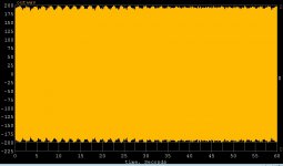
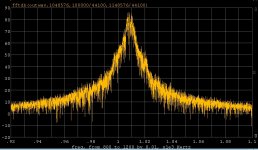
Here is a quick demo of why FFT techniques probably don't work well for this. There is substantial AM as well as FM, which you can see from the first plot which is the waveform after a simple 20dB (Q of 10) peaking equalizer at 1kHz. This is a 60sec 1kHz tone from the RCA STR100 test record. The second plot is a 1M point FFT zoomed in to show about .8% offset and lots of AM/FM sidebands (the 10Hz ones from cantilever oscillation). Beautiful isn't it?
Interesting that folks worry about close in jitter on their DAC's or even the dreaded PIM. 🙄
@Jan a quick scan to find zero crossings (interpolation works without a limiter) would yield a plot of instantaneous frequency, here at 1000 points per second for 500Hz resolution which is more than enough.
EDIT - The shape of the second plot is not from the filter, on this scale the filter was much wider.
Attachments
Last edited:
@scott wurcer,
Sorry, may be I am wrong. I thought @billshurv wanted to make the tonearm for measuring the eccentricity in the outrun groove of the records. That "tonearm" has to be rigid from the tip of the stylus to the arm bearing. Otherwise the red laser dot will show too much deviation when someone rotates the record not very, very slowly.
Sorry, may be I am wrong. I thought @billshurv wanted to make the tonearm for measuring the eccentricity in the outrun groove of the records. That "tonearm" has to be rigid from the tip of the stylus to the arm bearing. Otherwise the red laser dot will show too much deviation when someone rotates the record not very, very slowly.
@scott wurcer,
Sorry, may be I am wrong. I thought @billshurv wanted to make the tonearm for measuring the eccentricity in the outrun groove of the records. That "tonearm" has to be rigid from the tip of the stylus to the arm bearing. Otherwise the red laser dot will show too much deviation when someone rotates the record not very, very slowly.
I missed that you were addressing his particular application.
@scott wurcer,
Sorry, may be I am wrong. I thought @billshurv wanted to make the tonearm for measuring the eccentricity in the outrun groove of the records. That "tonearm" has to be rigid from the tip of the stylus to the arm bearing. Otherwise the red laser dot will show too much deviation when someone rotates the record not very, very slowly.
That is why I mentioned the Renishaw. It allows actual non contact measurement of the tonearm position throughout the playback process.
jn
- Status
- Not open for further replies.
- Home
- Source & Line
- Analogue Source
- Centering eccentric vinyl records