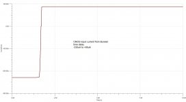
Yes it is indeed CMOS not TTL. But the +/-20mA input current limit still applies, so the 49k9 resistors still limit input current to a hundred uA or so.
Indeed. Note, if the circuit were to use actual TTL (open emitter input) it would probably not work as is.
Thor
Indeed. Note, if the circuit were to use actual TTL (open emitter input) it would probably not work as is.
Another issue with doing that way is that the 5V supply needs to absorb the clamping current, or the PSU will be pumped up and may even damage the IC. A zener diode on the psu line is good insurance, especially if a lot of logic ic's use the same rail.
Thor
Two 74HC14. One per channel. They run from a vanilla 7805 from the +28V regulated line coming in. So not much current draw at all.
I'm not sure if the 7805 has a minimum current to regulate, like the 317/337 do. There are a few searchable references that suggest 5mA is needed from a 7805 to ensure regulation, but that figure is not in the datasheets. A simple resistor of 1k or so would ensure that.
I'm not sure if the 7805 has a minimum current to regulate, like the 317/337 do. There are a few searchable references that suggest 5mA is needed from a 7805 to ensure regulation, but that figure is not in the datasheets. A simple resistor of 1k or so would ensure that.
Two 74HC14. One per channel. They run from a vanilla 7805 from the +28V regulated line coming in. So not much current draw at all.
Yup, static CMOS is basically "zero power".
I'm not sure if the 7805 has a minimum current to regulate, like the 317/337 do.
I think it has a little internal current and may be able to sink a few 100uA via Q6 and R19/20.
Thor
Great post Thor! Lots of good information in it, please keep sharing info like this! I really like what you said about ferrite. Thank you!Problems?
Ok. Give you an example.
Output filters cause problems. Enclosing them in a feedback loop helps audio band frequency response variations, but makes fixed frequency designs (clock locked to a digital input) difficult.
Worse, common output filters leak a lot of of the switching / carrier frequency. I will use "Carrier" from here-on, as this will make it easier for RF people to catch on.
Let's have a 400kHz switching amplifier with 100W/8Ohm and a 40kHz -3dB point for our output filter, a critically damped 2nd order lowpass. We will already see more than 1dB attenuation at 20kHz and our carrier attenuation will be 40dB. With a 80V PP carrier we see 0.8V carrier from a low source impedance.
But actually our self oscillating amplifier varies switching frequency with level, delivering rated power will likely leave us with 160kHz or so switching frequency, meaning our filter now filters only 24dB, so 80V PP become ~ 4V PP across the load, from a low impedance.
It certainly means using an AP2 to test such a class D amplifier shows huge THD & N that is highly variable with signal. But we just use an AUX-0025 filter and we no longer "see" this carrier leakage. And out of sight is out of mind and out of mind does not exist. Anyway, even if our speaker could respond to (say) 160kHz no listener could hear it, right?
Not so fast. Ferrite cored output inductors add distortion because of hysteresis. It was recently "discovered" by a Famous class D amplifier designer who "solved it by adding more negative feedback.
And yes, the core nonlinearities give rise to intermodulation between carrier and signal. And adding a lot of extra feedback around this will not really solve this. Worse, as the IM frequency is signal variable we will not see the result in a heavily averaged FFT, we would only see this with a fixed carrier.
But hey, it should not matter anyway, right?
Depends.
Let's look at a typical tweeter. It is a coil wound around a solid steel core. This gives rise to eddy current distortion, that is cubic functions with level and frequency. Given the level of carrier breakthrough into this nonlinear system with music is likely much higher than actual signal levels, audible results percieved as fidelity impairment are possible.
ANY linear Amplifier, even underbiased class AB will be from this impairment and the impairment cannot be directly determined testing only the individual device, but must be tested in the system.
A test could look at the current in the voice coil of a suitable tweeter with crossover, as current in the voice coil is a directl proxy of the force driving the diaphragm. The acoustic output cannot be lower distortion than this, excluding cancellation effects (which lower THD but tends to raise individual harmonics).
I do not consider "lowest THD" as a valid design goal. There is no proven correlation between low (lower than needed to be inaudible) THD and perceived "good sound" or a perception of "reduced fidelity impairment" or a perception of "improved fidelity". Thus it is pointless.
It reminds me of the old story of the drunk guy apparently looking for something under a streetlight. When the Cop asks him he tells the cop he is looking for his house keys.
The Cop helps looking, after a few minutes the cop ask: "Are you sure you lost the keys here?".
The drunk guy points somewhere into the darkness and says: "No. I lost them over there!".
The Cop asks: "Then why are you looking here?".
The drunk guy replies: "The light is better is here, easier to search!".
Thor
Yup, static CMOS is basically "zero power".
I think it has a little internal current and may be able to sink a few 100uA via Q6 and R19/20.
Thor
I was a little wrong - there are in Burwen four LEDs too that draw power from +5V too. One to indicate power on (~8mA) and three to indicate EQ bypass, Blend on/off, and phase invert. So between ~8mA and ~32mA into the LEDs. The 7805 could therefore dissipate (28 - 5)x32mA. Add to that a stated quiescent current of 6mA to get a power dissipation of about 1W. It should not need heatsinking with junction-ambient for TO220 version at ~24C/W,
I was a little wrong - there are in Burwen four LEDs too that draw power from +5V too. One to indicate power on (~8mA) and three to indicate EQ bypass, Blend on/off, and phase invert. So between ~8mA and ~32mA into the LEDs.
That is more than enough to sink the clamp diode current of our little inverter.
I did not say that this was a problem in Mr. Burwen's design, only that it's a hidden gotcha when using logic clamping diodes intentionally as signal limiters because commonly series regulators do not sink current.
Thor
That is interesting. Out of curiosity I've been trying to model the power supply regulators in Burwen's design. The +22V refused to regulate in TINA-TI, Microcap and LT-Spice. It either stuck at ~8V or oscillated, depending on the simulation package. It worked in Tina-TI using the generic opamp, and finally worked properly using an OPA2134 FET input opamp.
The -22V line is still refusing to play ball.
The upshot is that the simulation of these regulators is entirely dependent on the opamp and linear regulator macro models. You can basically get any result you like. Stir it and make a wish.
Since they are simple, I might just build them and do some tests. I've all the bits kicking around.
That is interesting. Out of curiosity I've been trying to model the power supply regulators in Burwen's design. The +22V refused to regulate in TINA-TI, Microcap and LT-Spice. It either stuck at ~8V or oscillated, depending on the simulation package. It worked in Tina-TI using the generic opamp, and finally worked properly using an OPA2134 FET input opamp.
I would look at the LM317 / 337 Models.
And the 5532 Model.
I have used these in the same way as Mr. Burwen, but I always had a resistor in the feedback line and a capacitor from the Op-Amp output to inverting input which was fettled until the circuit was unconditionally stable I don't see these in Mr Burwen's schematics. The 317/337 is pretty fast but may be too slow.
I also had a 10mA load on the 317/337 by adding a 120 Ohm Resistor between out & Adj (which also adds 10mA "Class A Bias" to the op-amp output).
Or it may be necessary to "slug" the regulator output with enough capacitance and with the right ESR. I count 13uF per channel per rail, film apparently, plus a 1,000uF Electrolytic Cap. So perhaps add 26uF with around 1mOhm ESR to the regulator output and make sure to draw enough current during startup.
The 10V reference circuit also provides a slow start for the 10V reference applied to the positive regulator and the negative regulator is set to invert the 10V Reference.
As the Op-Amp's are supplied post-regulator this would normally need a startup circuit, the need of which is avoided by using LM317/337 as "pass transistor" but startup could be interesting in ways that might have a simulator fail to converge or get stuck in an invalid state the real circuit does not experience.
Thor
Good suggestions Thor. The 317/337 models I put into TinaTI were the TI ones. They are pretty detailed and cover start up, transient behavior and drop out.
But the opamps are what was in the simulator. LT spice did indeed fail to converge and needed some tweaking to get the thing to work.
Craig
But the opamps are what was in the simulator. LT spice did indeed fail to converge and needed some tweaking to get the thing to work.
Craig
TI has a lot of extra parts for TINA. They are under "Spice Macro" Tab:Good suggestions Thor. The 317/337 models I put into TinaTI were the TI ones. They are pretty detailed and cover start up, transient behavior and drop out.
But the opamps are what was in the simulator. LT spice did indeed fail to converge and needed some tweaking to get the thing to work.
Craig
Thor
Incidentally, my take on a similar regulator uses:
LM334 - as CCS for reference (or similar)
LM329 - as 6.9V reference
NJM5534 - as Op-Amp (add compensation for unity gain stability)
LM317 - as pass device
120 Ohm connected between ADJ & OUT of LM317
5534 Output to ADJ of LM317, the 120 Ohm in effect dumps an extra 10mA into the output.
-V goes to ground and +V to the regulated output voltage
LM334 is powered from the regulated output voltage, so reference noise is minimised
Reference voltage to +input via a voltage divider to give 5V VREF, cap on VREF / positive input
Feedback from resistive divider on output, the upper resistor is capacitively bypassed to keep noise gain at unity
1k resistor in line with the inverting input feedback, capacitor from Output to provide frequency compensation
A negative version with 337 was also used a few times.
If positive and negative regulators were used, the negative regulator used literal inversion of the positive output, so once the 553X start working the +/- supply track each other starting up. The big capacitor across the feedback resistor on the negative side means noise is still limited to the 5534.
Never realised was a version with cascoding transistor and zener diodes as 5534 PSU & Output level shifters to allow voltages in excess of the 37V rating of 317 and the 44V rating of NE5534. Also never tried were versions with paralleled 317's for greater current.
The power supply has very low noise (essentially 5534 noise) and due to the 5534 push-pull output can sink a modest amount of current, not only source. Output impedance is very low, but it is inductive in nature. So the correct output capacitor is recommended. Usually some kind of low ESR solid electrolyte capacitor, e.g. Os-Con of several 100uF usually has the right parameters.
Thor

I got the power supply regulator sim working. It was all down to choosing the right regulator model. Being a closed loop design with an opamp the modelling stability is all down to the models. Output noise in 20kHz bandwidth 2uV. You can of course do better with Jung superregulators, but it is nice to at least get the original design, at least in simulation, working.
The other thing that works fine, is the bit of the circuit to do with power sequencing of the output drivers. That involves a voltage sensor to detect when the -ve supply gets to more than -11V, and a MOSFET that is then triggered to apply +22V to the output drivers.
As far as the model is concerned, it predicted that the MOSFET oscillated; that is entirely possible and the reason that MOSFET power amps can self destruct.
The solution is an RC snubber from D to S (100 ohm, 0.1u) and a 10u capacitor across the load. Once that was done it works as stated by Burwen.
Craig
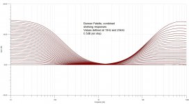
In Burwen's Audio Palette prototype, he adopts a quite different philosophy. There are four conventional boost and cut filters at 15Hz, 500Hz, 2kHz and 25kHz, with the same boost and cut levels as the final Cello unit.
But after this Burwen has a shelving filter section. This was quite deliberate; in fact his now defunct Bobcat software tone system had a combination of the two types of filter. In fact one of them is similar in operation to the Quad "Tilt" control of the 34 preamp. http://www.burwenbobcat.com/BBTB_Instructions.html
Anyway, in the philosophy of interesting reverse engineering, I've worked out the resistor chains to meet the Palette prototype shelving filters. Burwen states those in half dB steps at 15Hz and 25kHz.
First the response curves
Attachments
Craig,
Why would "one" want to shelve below 15hz and above 25Khz - regions that few can hear, and the vast majority of speakers can't reproduce? Not to mention what "information/music" is there there?
Why would "one" want to shelve below 15hz and above 25Khz - regions that few can hear, and the vast majority of speakers can't reproduce? Not to mention what "information/music" is there there?
In Burwen's Audio Palette prototype, he adopts a quite different philosophy. There are four conventional boost and cut filters at 15Hz, 500Hz, 2kHz and 25kHz, with the same boost and cut levels as the final Cello unit.
But after this Burwen has a shelving filter section. ... Burwen states those in half dB steps at 15Hz and 25kHz.
I would probably use "bell" curves at 125Hz/500Hz/2kHz/8kHz and LF/HF shelves at the extremes with the common ranges, maybe +/-4dB in the middle, +/- 8dB intermediate and +/-16dB for the shelving sections.
Using the 47 Pole Elma Switches this gives 0.7dB steps for shelves, 0.35dB and 0.18dB per step in the middle.
Thor
- Home
- Source & Line
- Analog Line Level
- Cello Palette Style EQ Design (was High End Tone Control)...