With double-plated boards throughout, having to remove two massive internal heathsinks with 6 power trans on each in order to look at the PCB traces, four main boards and at least two smaller ones, some caps without markings which would have to be unsoldered and measured to derive the values... I don't think so. I think there is enough reason here as to why nobody has drawn the schematics for this one (schematics for the Quad 405 mkI and mkII used to be a dime a dozen even back in the 80s...)
The Duet has power-on delay relays which helps to minimize surges on the speaker's end. I use old (not very good) speakers for any kind of testing with the amp, as I know how much it costs to repair the B&Ws.
You are right on the issue of "not knowing what it does" - except that I knew that the pot on the main output board was supposed to be for bias adjustement, and was measuring the voltage drop and quiescent voltage throughout my testing. It is certainly not a very good idea to turn knobs blindly - but I was monitoring the voltages very carefully with three different meters strategically placed at the same time. The voltages never got beyond 100 mV.
Cleiber
Sounds like a lot of fun! You can send it to me, I'll do it for you 😀
In case I cannot get it running again, I will take responsibility for proper disposal 😀 (ja, ja I know that's ZenMods job).
Have fun, Hannes
In case I cannot get it running again, I will take responsibility for proper disposal 😀 (ja, ja I know that's ZenMods job).
Have fun, Hannes
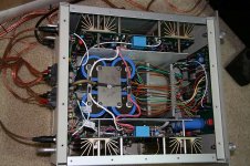
A complete values/parts list plus a picture of the other side of the transconductance stage opamp board should be sufficient.
I like this sandwiched toroid idea. perhaps I'll rotate it 90 degrees and try and make my F4 mono blocks nice and thin. Any reason this is a bad idea?
Ask Zenny about his collection of Harman classics : http://manuals.harman.com/hk/Service Manual/hk770 sm.pdf
jacco vermeulen said:A complete values/parts list plus a picture of the other side of the transconductance stage opamp board should be sufficient.
Does that mean you are only interested in the schematics for the little board in the jpeg and not the main board?
Trying to isolate the problem, it appears to be with the main board. The other channel measured well, and I was able to adjust the bias to the original specs (thanks, Hannes) - quiescent voltage less than 2 mV. And that is with the VAS board I repaired.
I don't want to assume anything since I don't have the schematics - but the main boards look identical. Do any of you know if in these amps it would be safe to swap left main board with right main board for testing?
(I know, I know - Hannes is going to think it is yet another stupid idea...) 😉
Cleiber
h_a said:
PS: I have no idea why an amp must be connected to anything for bias+offset adjustment and honestly I don't remember one which demanded that. Also I would not feel very comfortable with such a thing, since that obviously means that at every power on a DC-surge would be sent through the speakers.
Nevertheless, using a cheap 3W power resistor would have been the safe solution if you insist on a load.
I have read in several places now that specially with tube (valve) amps, a resistive load while testing is imperative. Is this not your understanding?
Chucks... The boards have the same numbers, everything is identical... except for one of the leads that connects to the input/output board. By reversing the boards, the lead is now on the other side, of course - and farther away from the i/o board, and so it doesn't quite reach. And it is soldered and clamped on, so it will be a pain to swap.
Need to go rummage around and see if I can find anything that might work as an extension lead... How frustrating...
Need to go rummage around and see if I can find anything that might work as an extension lead... How frustrating...
Well, isn't life interesting...
The main board that refused to warm up or be adjusted properly lit up like a Christmas tree once it was on the other channel. Adjusted beautifully, both voltage and bias. Obviously it is not the culprit - all the output trans also tested well, and are all very well matched indeed.
Have traced the problem either to the EPB board (unlikely) or the i/o board (more likely). Next step will be transistor and cap testing on the i/o board.
Three cheers for stupid ideas... 😀
Cleiber said:
I have read in several places now that specially with tube (valve) amps, a resistive load while testing is imperative. Is this not your understanding?
As a matter of fact - one of the places I read one shouldn't operate this kind of amp with open inputs was right here on this thread (!!) - Post # 21 by Qserra Tico Tico, in reply to a post about ... the Cello Duet 350!!
Fancy that...

Hi Cleiber!
Naah, no open inputs are imperative only noise-wise. Means, do not measure noise with open inputs. Do not listen to music with open inputs, since RF could be picked up - which can give rise to annoying noise of all sorts.
I assumed you did already short unused inputs?
All the best, Hannes
Naah, no open inputs are imperative only noise-wise. Means, do not measure noise with open inputs. Do not listen to music with open inputs, since RF could be picked up - which can give rise to annoying noise of all sorts.
I assumed you did already short unused inputs?
All the best, Hannes
Yep - I took two XLR connectors and soldered both live pins to ground (the Duet has balanced inputs).
With less than $3 worth of parts and another 1/2 hour on the work bench, the Duet appears to now be sounding like it should. Bias and standing voltage are behaving normally on both channels, both channels are giving off heath, and I can't remember when this unit sounded this good.
Obviously looks like the i/o problem developed at some stage earlier on, and it wasn't till the pops and crackles that I realized something else was wrong with the unit (I remember thinking something wasn't quite right with it a while back, but I haven't used the Duet in quite a while).
Of course, I am expecting smoke to start rising out of the unit any time now - - but at least for this last hour or so I have been able to listen to it working well.
Please keep your collective fingers crossed...
Cleiber
Obviously looks like the i/o problem developed at some stage earlier on, and it wasn't till the pops and crackles that I realized something else was wrong with the unit (I remember thinking something wasn't quite right with it a while back, but I haven't used the Duet in quite a while).
Of course, I am expecting smoke to start rising out of the unit any time now -
- but at least for this last hour or so I have been able to listen to it working well.Please keep your collective fingers crossed...
Cleiber
After playing with those boards for a while, I realized that my VAS boards were version 1 - whereas the last boards made were version 7 design (PCB version 3). Several parts on the version 1 boards are no longer available. Paul at Viola labs had a few of the latest boards left, so we bought two of them and they appear to be working very well after installation. Hopefully this will help give this old Duet a new lease of life.
Need Cello Performance (II) schematics
I have recapped and have them at a tech who needs schematics. (Hours have been spent, one amp shuts down on turn on.
I have recapped and have them at a tech who needs schematics. (Hours have been spent, one amp shuts down on turn on.
Cello Duet Troubleshooting
I am experiencing the same issue with my Cello Duet and it looks like no one is offering support. I am a EE, so if anyone has advice or a schematic, please let me know! I get a static sound out of the right channel. Randomly, the sound is loud and the breaker trips.
Thanks,
Erik
I am experiencing the same issue with my Cello Duet and it looks like no one is offering support. I am a EE, so if anyone has advice or a schematic, please let me know! I get a static sound out of the right channel. Randomly, the sound is loud and the breaker trips.
Thanks,
Erik
- Status
- Not open for further replies.
- Home
- Amplifiers
- Solid State
- Cello Amplifier troubleshooting