I had a similar issue with a SAE amp some time ago.
It sounds like a stability issue with aging capacitors
imac
It sounds like a stability issue with aging capacitors
imac
ppa said:There are an error in the cello encore schematic.
Hi PP
What is the error? Please advice.
Best Regards
Guys, it's written just a few posts above!
The most important error is
All the best, Hannes
The most important error is
The dot on the emitter of Q7 and the collector of Q8 is missing indeed.
All the best, Hannes
When I have told "There are" instead "there is" is a "Freudian slip" , infact there are several errors in the second schematic:
Look the differences between the first and the second schematic, the first is correct.
PP
Look the differences between the first and the second schematic, the first is correct.
PP
Well, back to cats instead of rats... I think... 🙂
Got about $50 worth of parts, mostly same specs as the ones in the Cello (quite a few are Mil-Spec). Replaced the electrolictic and some other caps, a few transistors, and a few resistors for good measure (I had "smoked" a couple of them trying out something I absolutely shouldn't have).
Quite hard dealing with double-sided plated-through boards with old solder, but managed to get the parts I thought needed replacing on to the board. So far, works beautifully and no crackles and pops as yet...
Will keep y'all posted, if anyone is interested.
Cleiber
Hmmm....
It appears that the main power transistors in the "fixed" channel are running considerably cooler than the the other channel (heatsinks are nowhere near as hot). The sound appears to be OK from both channels, and similar in volume and quality.
I believe the Duet is a pure "class A" and should be running "hot" even when there is no signal. This doesn't make much sense.
Comments?
Cleiber
The Duet a 350W Class A amp ??
That would mean heatsinks as large as a washing machine.
The 350W duet is ClassAB2 as Cello calls it, see here
So just a tiny amount of ClassA to reduce crossover distortion (several 10s of mA).
By the way, I hope you didn't change transistors that need to be matched. Would be a pity to unnecessarily kill the performance of the amp. But without a schematic impossible to say - however the outputs are definitely matched. If you changed e.g. the drivers with different parts bias readjustment could be necessary.
A few things come to my mind: the tiny bandwidth that this amp has; I do not remember another amp that goes already 1dB down at 20kHz. 2nd, it was largely argued by Colangelo that a high input impedance is beneficial, though the inverting input is again - as in the Encore - of rather low impedance (5k). Gain is also a bit high (just as in the Encore).
I'm wondering wether this Duet has the same interesting topology details as the Encore* has or wether it is more convential.
All the best, Hannes
* don't forget the Encore was the heart of the Performance, top of the line Cello-amp.
h_a said:interesting topology
Same zero NFB output stage is what the THD numbers of the Duet indicate, likely also the reason for the steep roll-off.
The Duet output stage with 6 output devices in parallel probably has 0.33 ohm emitter resistors, means at least 60W of dissipation per channel for close to 90V rails.
Personally i can not imagine anyone not hearing a difference between an optimal Class AB and a close to B biased channel of such a power amp.
(a regular Class AB biased solid state amp is Class AB2, a VFET output stage would be AB1)
h_a said:
By the way, I hope you didn't change transistors that need to be matched. Would be a pity to unnecessarily kill the performance of the amp. But without a schematic impossible to say - however the outputs are definitely matched. If you changed e.g. the drivers with different parts bias readjustment could be necessary.
Hannes,
The transistors changed were in the voltage gain amplifier board, which is a small board piggy-backed onto the main output board. Transistors changed were 2 x 2N5416 and 2 x 2N3439, and the capcitors around them (please see jpeg below).
Matching could be the reason - maybe the bias is off with the new parts. Still, it doesn't sound strange as yet. I will be using some of my test tracks later on tonight to carefully listen to what is going on.
Thanks,
Cleiber
Attachments
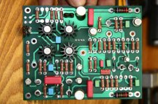
Well, certainly I can only guess. PCB-layout looks a bit like the Encore's, also the used parts are the same. Seems you changed - as you said - the VAS parts. If a current mirror is used in the Duet - it seems so - matched bipolars for the VAS are not necessary.
However these parts are not particularly stressed thermally (less than 1 W in the Encore), so I doubt that they're broken. But lets hope your problem is gone!
Well, it's all guessing at the moment.
Unfortunately your problem sounds like a tough one (even if one would have the schematic).
All the best, Hannes
PS: funny, seems they used again the U403 at the input.
EDIT: oh I forgot: the drivers are not on this board, so output bias is most likely unchanged.
h_a said:Well, certainly I can only guess. PCB-layout looks a bit like the Encore's, also the used parts are the same. Seems you changed - as you said - the VAS parts. If a current mirror is used in the Duet - it seems so - matched bipolars for the VAS are not necessary.
However these parts are not particularly stressed thermally (less than 1 W in the Encore), so I doubt that they're broken. But lets hope your problem is gone!
Well, it's all guessing at the moment.
Unfortunately your problem sounds like a tough one (even if one would have the schematic).
All the best, Hannes
PS: funny, seems they used again the U403 at the input.
EDIT: oh I forgot: the drivers are not on this board, so output bias is most likely unchanged.
Well, yes - the main drivers are on the main board, which this board on the jpeg connects to. I am listening to some of the tracks I have produced/engineered, and they sound just fine through the B&Ws. A "mono" test also seems to be fine. However, the channel that was "fixed" still is running much cooler on the heatshsinks than the other channel's.
Should an AB2 amplifier run hot all the time, even with no signal? I find this pretty strange - although I cannot be sure if both channels were running at similar temperatures before the "fix". The board in the JPEG is the Voltage Gain Amplifier board. I might swap this board with the other channel to see if the cooler running goes with it.
What is U403 you were referring to?
Thanks and all best,
Cleiber
The plot does thicken...
Exchanged the VGA boards between channels. The heathsinks still behave the same way - in other words, the cool heathsink didn't "go" to the other channel with the VGA board.
Something else must have gone wrong on the "fixed" channel's main output board, or the amp is just playing around with me. The sound appears to be exactly the same on both channels, even when swapping speakers.
????
Cleiber
Hi Cleiber,
I'm sorry that I wasn't clear on the heat issue.
Just general comment: the temperature of the heatsink is determined by the bias current set for the output devices. The bias is usually - also in the Encore - set by a trimpot mounted close to the output devices.
The VAS you swapped does not set the output stage bias; so swapping them does not have an effect, just as you found out.
What you need to do is to measure the voltage across the emitter resistors of the output devices _of the working channel_ and adjust the trim pot of the _other channel_ so that you get the same voltage drop across the emitter resistors of the other channel.
However that has still the problem that you don't know if not both channels need readjustment. I will mail you an email-adress, maybe he has the details on the correct bias.
But all of this has nothing to do with your crackling problem. I would recommend you to stop changing parts blindly.
Have fun, Hannes
Hannes,
Thanks for the post. I wasn't very clear about the problems, as there obviously appeared to be two of them. The crackling and poping has gone after the replacement of the parts on the VGA board. It sounded like a cap issue (there was some wistling as well with the crackles, which seemed to point to a cap problem) - so looks like that problem is now solved. Not a single crackle or pop since the repair. I noticed the heath difference problem after the repair, but it seems to actually have been there since I acquired the unit. Just went back and read some notes I made back when I bought it, and it looks like I noticed more heat coming off one side of the amp than the other.
Measuring the bias current, as you suggest, might be a good way to start on this problem.
Many thanks again for your input,
Cleiber
Something is definitely funny with this amp.
Read a bit about bias and DC offset - one of the tests listed was to check the quiescent voltage across the speaker posts. One channel is reading 1.4 mV, the other one 50.2 mV. On the latter (the "cooler" channel), turning the adjustable pot (the only one on the main output board) changes the voltage, but it doesn't go below 30 mV or so. On the other channel (the one that runs "hot") turning the adjustable pot makes no difference whatsoever to the voltage.
The only other adjustable pot I can see is in the VAS (VGA?) board, and I have not tried adjusting that - since swapping these boards between channels made no difference as to how hot the output trans. heathsinks got.
There has got to be another problem here somewhere...
Cleiber

PS.: I am correct in that these measurements should be made with the speakers connected, and also with the preamp connected, correct?
Read a bit about bias and DC offset - one of the tests listed was to check the quiescent voltage across the speaker posts. One channel is reading 1.4 mV, the other one 50.2 mV. On the latter (the "cooler" channel), turning the adjustable pot (the only one on the main output board) changes the voltage, but it doesn't go below 30 mV or so. On the other channel (the one that runs "hot") turning the adjustable pot makes no difference whatsoever to the voltage.
The only other adjustable pot I can see is in the VAS (VGA?) board, and I have not tried adjusting that - since swapping these boards between channels made no difference as to how hot the output trans. heathsinks got.
There has got to be another problem here somewhere...
Cleiber
PS.: I am correct in that these measurements should be made with the speakers connected, and also with the preamp connected, correct?
Cleiber, you're a fearless guy. 😱
Thinking of the worth of your amp and speakers I'm surprised what you do on your own and tell here afterwards.
No, no, no.
Preamp connected or not does not matter.
And dettach the speakers first!!
If you would have touched the pot on the frontend board, you could have caused several volts offset! Maybe it won't kill your speakers straight away, but it won't be beneficial for sure.
The pot on the output stage is for bias! It should not affect offset voltage.
I can only recomend you to stop fiddling with the amp. If you're unhappy with its performance bring it to some electronic service shop and get it done professionally. With your combination of lacking knowledge and fearlessness you're quite short of destroying something.
Won't be fun, Hannes
PS: by the way offset below 50mA is perfectly normal.
Well, i thought this was the DIY forum, isn't it? 😀
As for my lack of knowledge, I have been working with electronics for over 35 years. I am also a radio amateur, with considerable experience in working with radios and RF amps. My recollection of audio amplification (I worked on them some in the 70s) is a bit rusty and I worked mostly with Quad equipment - no A or AB - but that doesn't mean that I am totally careless or unkowledgeable. I followed the procedures I read, supposedly written by an expert - and frankly, measuring offset voltage and voltage drop across resistors is an extremelly simple procedure - at least for me.
Since I am perfect capable of measuring these values, please do let me know where it is that I am being "fearless"? The OC11 board got fixed quite well, thank you - and I have routinely fixed several other electronic items here - from computers to a lot of other old audio gear.
Thanks again for you help.
Cleiber
PS.: I seem to have specifically read here and elsewhere that you should NOT test one of these types of amps without some resistive load across the inputs. I may have misunderstood the outputs, but it is not unreasonable to assume that you would need your load there too in order to measure operating voltage, is it? After all, the voltage meter's impedence could be quite different from unit to unit - or does that not matter in this case?
Oh yes, I forgot. One of the reasons I said there is something "funny" with this amp is precisely because the offset voltage *does* change with the bias pot regulation. BTW, I was very careful to measure the resistance across the pot so I was able to return it to the original ohms reading.
There is only one company I am aware of that I would trust to work this amp. According to several Duet owners I have known over the years, that is Viola Labs. The company that took over the Cello name does not build amplifiers any longer, and the guys at Viola apparently include some of the engineers, such as Paul Jayson, who - if memory serves - worked with Mark L on the original Cello Duet, Encore and Performance design. I wouldn't trust a generic electronic shop - or even an engineer - to be able to diagnose major problems on this unit without the schematics and service manual.
All best,
Cleiber
Well, of course I'm sorry that I made you feel bad. My intention was solely to warn you of the potential damage to you and your equipment - as it seemed to me that you're too little aware of what you're exactly doing. Not a good idea, not even with cheap gear.
I also wonder now with your skills why don't you bother to derive a schematic of your amp? Every discussion and advice would be far easier and more reliable than the plain guessing at the moment.
Further I would think that with your experience you would never touch potis without knowing what they do.
I think the only reasonable way to tackle this problem would be to draw a schematic, calculate working points and measure both channels. Then you can fix it and finally adjust offset and bias.
All the best, Hannes
PS: I have no idea why an amp must be connected to anything for bias+offset adjustment and honestly I don't remember one which demanded that. Also I would not feel very comfortable with such a thing, since that obviously means that at every power on a DC-surge would be sent through the speakers.
Nevertheless, using a cheap 3W power resistor would have been the safe solution if you insist on a load.
- Status
- Not open for further replies.
- Home
- Amplifiers
- Solid State
- Cello Amplifier troubleshooting