got one of the 2604s in (on the small pcb) and has really breathed fresh air into the vocals, and even better 3d imaging, loving this, just waiting for the other chips, for the two below the small pcb, then its time to do all the caps (electro only obviously)
Something else occured to me on this player. How does it mute ? If there are no physical relays in it, then it will almost certainly use transistors to mute the audio by shorting the outputs to ground. It's common practice, but there's a lot of controversy as too whether this method creates problems sonically. It's something I've never investigated, my Micromega uses a relay, and my amp uses FET's for analogue switching.
The point is that there was a thread where this got mentioned, the player had an audio fault, and I suspected the mute transistors, which in the end were the fault, however stephensank recommended replacing them with FET's... and you could do the same if yours is similar.
http://www.diyaudio.com/forums/digi...sa8001-modification-eliminate-distortion.html
The best thing is to remove them altogether and see if you hear any difference bearing in mind you will get clicks at the start of discs etc without them.
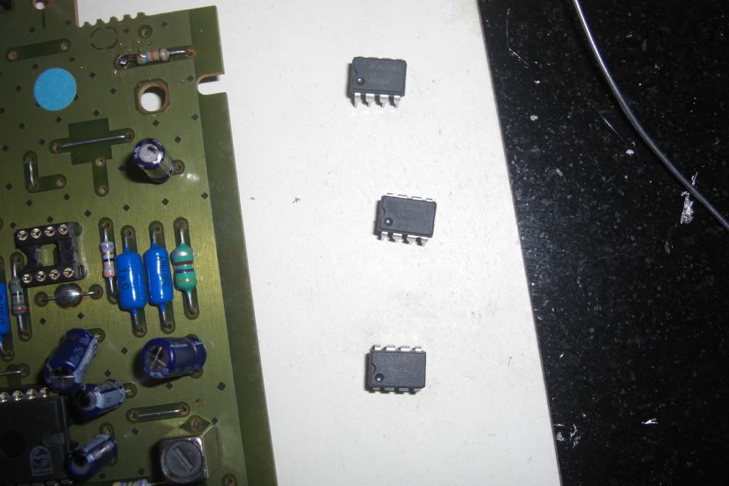
yea got the IC sockets and the caps neatly soldered on pins 4 and 8. When the other chips arrive, I will take some pics.
Ah I see, about the mute idea, very interesting indeed, so it wont harm the player if I remove the FETs? would you know if I took a photo the rough area?
Sounds like a good plan though, chips should be here tomorrow, and have priced up to replace all the remaining caps as well with Silmic IIs.
Considering the player cost me £25 and with the total cost of upgrades being around £60 its becoming a bargain top sounding player. Its already souding like twice its retail value (which was about £800 in 93') and I dont want to stop anytime soon.
It will be my learning CD player which I can tell my kids about, ha ha, I have two girls and they already moan at my love for all things hifi. My 5 year old told me the other day that I love my speakers more than them, well not quite, but nearly darling, ha ha.😀😀
Lol 🙂
Bit of a bargain for £25...
I'm guessing that it follows Philips practice of using bjts (ordinary 🙂) transistors and not FET's.
A close up of the underside of the PCB might help. The transistors may be surface mount types, but they will short the output to ground.
If in doubt don't touch 🙂
Bit of a bargain for £25...
I'm guessing that it follows Philips practice of using bjts (ordinary 🙂) transistors and not FET's.
A close up of the underside of the PCB might help. The transistors may be surface mount types, but they will short the output to ground.
If in doubt don't touch 🙂
This is from a Sony Minidisc recorder... note the similarity to a CD player output stage. See the mute transistors at the left... when they turn on they just short the audio to ground... problem is it's not a "good" way to use a transistor... but it's cheap and it works. A FET is far better as it works entirely differently.
So if you can identify that area of the circuit by tracing the audio back from the outputs then you should see how the Orelle achieve it's muting. The transistors may be very tiny and soldered to the underside of the PCB and they could even be FET's anyway as it's an upmarket machine. A voltage chaeck on the base of the transistor in use would confirm yay or nay for that.
Fit your opamps first and think about this later... Just look and investigate for now I would say.
That's me done for tonight 🙂
Attachments
thanks mooly, will certainly move onto that after the Opamps, as I dont really want to stop learning on this, keeping my brain buzzing, have not enjoyed electronics as much..........umm.............wait, oh yea ever like this before.
Thanks for making it interesting again, combining my love of audio, and the constant want to upgrade, but for CHEAP, which amazes me more TBH
Night night, speak soon.
Thanks for making it interesting again, combining my love of audio, and the constant want to upgrade, but for CHEAP, which amazes me more TBH
Night night, speak soon.
Last edited:
You can't tell by looking.
And I'm wrong there saying a quick voltage check would confirm. Some transistors have in built bias resistor networks so you can't get at the "base" to read the voltage on there directly... always ways and means though. And it's a Philips PCB, it's going to be "ordinary" transistors I bet.
It's just something to think on as I say... you mod the player with the opamps first 🙂
Can you see how they connect the audio "to ground" When they turn on (when told by the microprocessor) they short the outputs to ground killing noise and clicks etc
Think that I found the tiny mute transistors. Some pics below, what do you think?
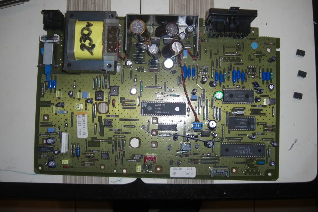
In the meantime here is the last of the current mods (end of month replacing all the caps)
The caps below the small PCB are going to stay I think as they are hard to remove.
All the Opamps are 4562s at the moment, but going to swap around the top opamp.

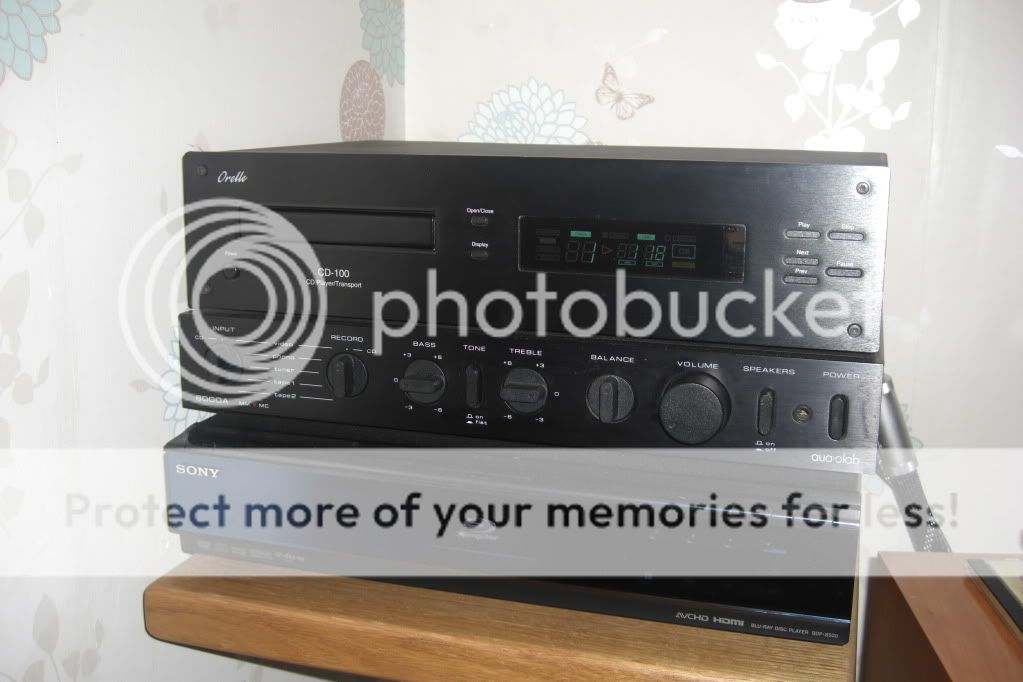
my modest hifi
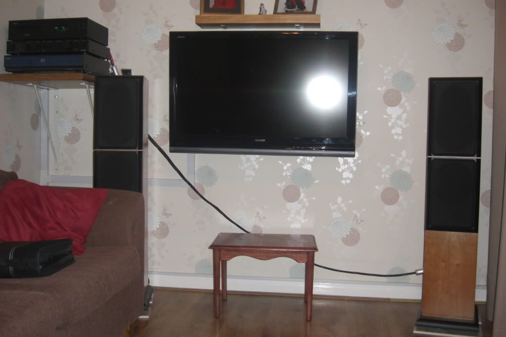
my general setup
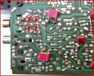
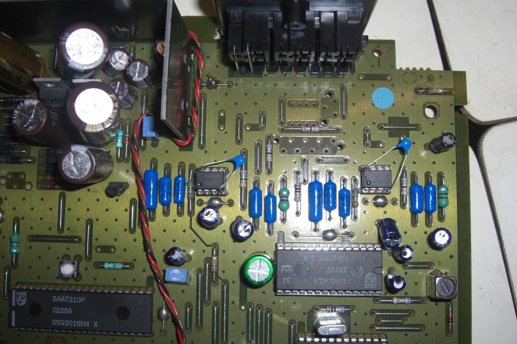
last pic, lot of flash, but can you see the small transistors (think that they are the mute ones) to the left and the right
In the meantime here is the last of the current mods (end of month replacing all the caps)
The caps below the small PCB are going to stay I think as they are hard to remove.
All the Opamps are 4562s at the moment, but going to swap around the top opamp.
my modest hifi
my general setup
last pic, lot of flash, but can you see the small transistors (think that they are the mute ones) to the left and the right
Last edited:
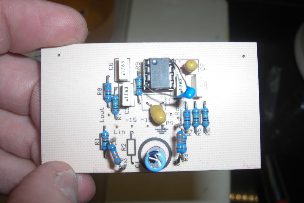
It's looking good... see you have the small decoupling caps fitted on the IC's.
Be interesting to know your impressions of the LM4562 vs the OPA2604. The two on the main PCB have to be kept the same of course (left and right)
That add on PCB looks like it's used to replace an opamp that's not fitted on the main board.
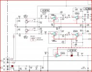
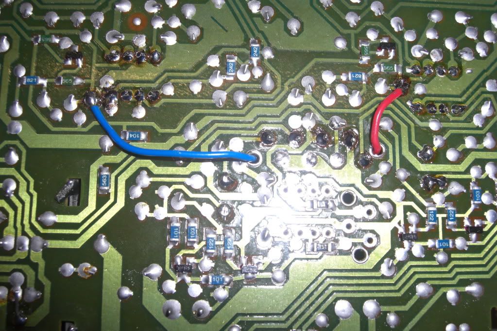
Without seeing the whole thing it's a bit more difficult putting it all together. The four transistors at the bottom in your piccy (one off the right edge) are the mute transistors. They actually go to pin 1 ? (that I can see) on the unused chip and pin 7 ?
So does the output of that add on board feed into those points ?
The four resistors marked 122. It looks like the "top" of all those four join together... that's the mute on/off logic line for the left and right channel if so.
If you can identify on the top of the PCB the connection or link etc that goes to those resistors, then when the player is working you can measure the voltage on that line and see what happens and what voltage it goes to in mute and play etc.
Be interesting to know your impressions of the LM4562 vs the OPA2604. The two on the main PCB have to be kept the same of course (left and right)
That add on PCB looks like it's used to replace an opamp that's not fitted on the main board.
Without seeing the whole thing it's a bit more difficult putting it all together. The four transistors at the bottom in your piccy (one off the right edge) are the mute transistors. They actually go to pin 1 ? (that I can see) on the unused chip and pin 7 ?
So does the output of that add on board feed into those points ?
The four resistors marked 122. It looks like the "top" of all those four join together... that's the mute on/off logic line for the left and right channel if so.
If you can identify on the top of the PCB the connection or link etc that goes to those resistors, then when the player is working you can measure the voltage on that line and see what happens and what voltage it goes to in mute and play etc.
I do like the sound of the 4562s, they are exactly as you said, give and take nothing away.
I might try the 2604 tonight on the top PCB. The only trouble is, changing the lower chips, under the PCB means that I have to remove that PCB everytime, which is a little awkward.
I think that the 2604 sounded a little warmer, and, yes as you say again, a little more coloured, in a good way of course.
The 4562s give such clarity and detail that I have never heard before, even when I had my Meridian system and Quad electrostat speakers !!
Dear Mooly, Graham,
very good news. my 1 channel noise problem (#249) solved today, turn out to be a broken pad on one of decoupling cap..yihaaa..🙂. I've learned yet another lesson. Now I can relax and enjoy this thread
thanks
TeguhPS
very good news. my 1 channel noise problem (#249) solved today, turn out to be a broken pad on one of decoupling cap..yihaaa..🙂. I've learned yet another lesson. Now I can relax and enjoy this thread
thanks
TeguhPS
Experimenting with the opamps is interesting, and remember there is no right and wrong, it's what you prefer that matters.
Dear Mooly, Graham,
very good news. my 1 channel noise problem (#249) solved today, turn out to be a broken pad on one of decoupling cap..yihaaa..🙂. I've learned yet another lesson. Now I can relax and enjoy this thread
thanks
TeguhPS
Thats great news, yea sit back and enjoy, for me it sounded even better knowing, with some considerable help 😱 that the music sounds better after you have fixed it.
Mooly, you are exactly right, experimenting is half the fun, I doubt that I will ever think that one sounds better than the other, only different for different reasons.
Let the listening commence 😎
mmm liking the mix of both opamps, giving a clean sound and yet a little less clinical, it depends what mood I am in, and to be honest, what I am listening to.
Think it will be soon time to add a better power amp, think that will have to wait until christmas time though.
Hmm now to upgrade the speakers, something that I know a little about, when will this DIYing stop.............hopefully never 😱😀
Think it will be soon time to add a better power amp, think that will have to wait until christmas time though.
Hmm now to upgrade the speakers, something that I know a little about, when will this DIYing stop.............hopefully never 😱😀
Finally managed to pull myself away from the music to give my opinion of the opamps that I am using.
Cut a long story short I have found a gorgeous combination, using both the opamps mentioned gives a beautiful sound, the clarity and clean sound of the 4562 (just that on its own and the music loses its, well toe tapping drive) and the musical upfront slightly warm sound of the 2604 is perfect for me.
On there own they are too much of each sound, but together, well, detail that I have never heard before along with the ability to listen to the music for hours and a tired hand and foot through tapping along, lovely.
- Status
- Not open for further replies.
- Home
- Source & Line
- Digital Source
- CD player with distortion. laser?