The add on board is definitely left and right, one of the opamps in the LF353 used for L and the other for R. I can tell that by the picture, everythings doubled up, two identical circuits.
There's no interaction between the two, they behave as totally separate devices.
There's no interaction between the two, they behave as totally separate devices.
Maplin NE5532,
NE5532N : OpAmps : Maplin
use the "store check" box... Yeovil, that near you ? has 1 🙂
NE5532N : OpAmps : Maplin
use the "store check" box... Yeovil, that near you ? has 1 🙂
Maplin NE5532,
NE5532N : OpAmps : Maplin
use the "store check" box... Yeovil, that near you ? has 1 🙂
yerp, go to Maplins when in need of something fast (its about 3 miles away), got me caps for the opamps from there for about 20pence each, also go the chip holders from there as well.
Hmm might just get that.
The add on board is definitely left and right, one of the opamps in the LF353 used for L and the other for R. I can tell that by the picture, everythings doubled up, two identical circuits.
There's no interaction between the two, they behave as totally separate devices.
I see, so the one opamp works both channels, what about the two below the add on circuit, are they used as well, I do hope so as I have just ordered some more opamps, will have opamp overload 😱, if I only need one. 😀
I am getting it slowly, understanding it that is, so the two under the circuit are double opamps (two amps in each ic) but they are only using one amp in each ic for left and right, do you think?
Dam, got to pick up a new tumble dryer later, as I just want to play with the CDP, oh well reality strikes. Still got a nice long weekend, as have tomorrow and Monday off, so hopefully chips will arrive then?
Dam, got to pick up a new tumble dryer later, as I just want to play with the CDP, oh well reality strikes. Still got a nice long weekend, as have tomorrow and Monday off, so hopefully chips will arrive then?
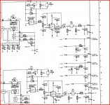
Here's the circuit of a Philips CD303 showing 4 opamps used in the analogue stages, these are NE5532 by the way. All the opamps are in use. Your player will be very very similar.
So four opamps are needed here for this design. They could have used four single opamps such as the NE5534 (look up the data sheet for pin outs) or 2 NE5532's which contain 2 opamps each.
You can also get packages with four opamps in each. so they could have used just one of those, but the choices are limited... not very good audio ones available in those.
So far so good... now, you can use any of those four opamps contained in the two IC's for any of the ones in that circuit... but it's logical when designing the thing to use one IC for one channel and one for the other. It's cheaper also to use dual IC's than singles, and it also takes up less space on the PCB. Remember each opamp (the individual one in the IC) is totally independant of the other. They only share the power pins.
It would be interesting on your player to see just how that extra PCB is wired. Does the output from that board, that's pins 1 and 7 of the IC go somehow to the output sockets ? Might go through a cap or two and a resistor etc on the way.
Do you know how opamps work... basic rules governing how they behave ?
Attachments
well this is definately going to keep me interested for my long weekend, get the orelle open tomorrow and see if I can follow the output pins from the single IC, see where it goes. loving learning every minute of this, hope you dont mind Mooly.
Dear all, (sorry Graham, for interrupting..)
I have spent many evenings reading this happy ending thread 🙂. I think I have similar problem as Graham. My restored Sony CDP M75 (tda 1541) distort faintly on left channel only. It is kind of distorsion that does not change in pattern for the same track and is repeatable.
I have Nos'ed the cdp - so its not the digital filter, changed the DAC same story, changed the decouplings & cap between pin 16-17 of TDA..changed the optic..the clock
All emphasis & mute transistors removed, opamp changed, changed the RF chip CXA1081, replaced 95% of electrolytes including coupling cap, reflowed almost whole pcb and chips ;::🙁
can it be the SRAM LC9600 causing this?..Appreciate your advices
Thanks
TeguhPS
no problem at all, I wish that I could help, but this is a little beyond me, but sure someone can, at least you have not given up, thats the main thing
yep, its beyond me as well, thanks & I'm going to follow your mod to happy (tube) ending 🙂
regards
TeguhPS
regards
TeguhPS
ide2003
Your probably better starting a new thread for this problem 🙂
TBH it doesn't really sound like the same problem. Faint distortion on one channel only sounds more like a problem in either the analogue stages, or a problem around one of the DAC's.
Really needs a 'scope to fault find. You could perhaps do very careful DC measurements on both channels DAC and output stages and compare.
Opamps... crash course
Just the very basics, but it covers 99% of applications.
The opamp has 3 main terminals, two inputs and an output. The two inputs are labelled - and + or inverting and non inverting.
Do you understand resistors, and how to make up a simple divider using them ?
For example, two equal value resistors in series connected across a 12 volt battery would each drop (or have across) them 6 volts. If you made one resistor 11R and the other 1R then there would be 11 volts across one and 1 volt across the other.
It's just ohms law.
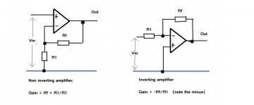
So have a look at the two opamps here.
The golden rule... an opamp with feedback (which is 99.9999% of applications in other words) will always try and make the difference between the two inputs equal zero.
Thats not the same as "making the inputs zero"... it's the "difference between" that is zero.
So the first opamp is connected as a non inverting stage. The input is applied to the + input.
The - input is connected to a resistive divider so it take a portion of the output voltage.
So if we put some numbers in, and lets say Rf =9R and R1 =1R.
That could be 9000 ohm and 1000 ohm or 9 million ohm and 1 million ohm... we are looking at the ratio of the two rather than the absolute values.
Remembering the golden rule, "keeping the difference between the inputs zero" can you see that if we apply 1 volt to the + input, then the output has to rise to 10 volts to bring the - input the same as the + thus maintaining the "zero difference.
If we applied -1 volt to the input then the output would have to go to -10 volts.
So with just one opamp and two resistors we have made an amp with a gain of 10... it really is that easy.
By varying the feedback factor which is the ratio of those two resistors we can make an amp with any gain we choose.
The inverting amp works in a similar way. Lets say R1 is 1R and RF is 10R.
If we apply 1 volt to the input, then the output has to go to -10 to keep the difference between the inputs zero. The output is inverted (-) Apply -1 volt to the input and we would get 10 volts out.
Just the very basics, but it covers 99% of applications.
The opamp has 3 main terminals, two inputs and an output. The two inputs are labelled - and + or inverting and non inverting.
Do you understand resistors, and how to make up a simple divider using them ?
For example, two equal value resistors in series connected across a 12 volt battery would each drop (or have across) them 6 volts. If you made one resistor 11R and the other 1R then there would be 11 volts across one and 1 volt across the other.
It's just ohms law.
So have a look at the two opamps here.
The golden rule... an opamp with feedback (which is 99.9999% of applications in other words) will always try and make the difference between the two inputs equal zero.
Thats not the same as "making the inputs zero"... it's the "difference between" that is zero.
So the first opamp is connected as a non inverting stage. The input is applied to the + input.
The - input is connected to a resistive divider so it take a portion of the output voltage.
So if we put some numbers in, and lets say Rf =9R and R1 =1R.
That could be 9000 ohm and 1000 ohm or 9 million ohm and 1 million ohm... we are looking at the ratio of the two rather than the absolute values.
Remembering the golden rule, "keeping the difference between the inputs zero" can you see that if we apply 1 volt to the + input, then the output has to rise to 10 volts to bring the - input the same as the + thus maintaining the "zero difference.
If we applied -1 volt to the input then the output would have to go to -10 volts.
So with just one opamp and two resistors we have made an amp with a gain of 10... it really is that easy.
By varying the feedback factor which is the ratio of those two resistors we can make an amp with any gain we choose.
The inverting amp works in a similar way. Lets say R1 is 1R and RF is 10R.
If we apply 1 volt to the input, then the output has to go to -10 to keep the difference between the inputs zero. The output is inverted (-) Apply -1 volt to the input and we would get 10 volts out.
Attachments
Your probably better starting a new thread for this problem 🙂
TBH it doesn't really sound like the same problem. Faint distortion on one channel only sounds more like a problem in either the analogue stages, or a problem around one of the DAC's.
Really needs a 'scope to fault find. You could perhaps do very careful DC measurements on both channels DAC and output stages and compare.
thanks Mooly, will start the thread soon, hopes you'll be there there
regards
TeguhPS
Just the very basics, but it covers 99% of applications.
The opamp has 3 main terminals, two inputs and an output. The two inputs are labelled - and + or inverting and non inverting.
Do you understand resistors, and how to make up a simple divider using them ?
For example, two equal value resistors in series connected across a 12 volt battery would each drop (or have across) them 6 volts. If you made one resistor 11R and the other 1R then there would be 11 volts across one and 1 volt across the other.
It's just ohms law.
So have a look at the two opamps here.
The golden rule... an opamp with feedback (which is 99.9999% of applications in other words) will always try and make the difference between the two inputs equal zero.
Thats not the same as "making the inputs zero"... it's the "difference between" that is zero.
So the first opamp is connected as a non inverting stage. The input is applied to the + input.
The - input is connected to a resistive divider so it take a portion of the output voltage.
So if we put some numbers in, and lets say Rf =9R and R1 =1R.
That could be 9000 ohm and 1000 ohm or 9 million ohm and 1 million ohm... we are looking at the ratio of the two rather than the absolute values.
Remembering the golden rule, "keeping the difference between the inputs zero" can you see that if we apply 1 volt to the + input, then the output has to rise to 10 volts to bring the - input the same as the + thus maintaining the "zero difference.
If we applied -1 volt to the input then the output would have to go to -10 volts.
So with just one opamp and two resistors we have made an amp with a gain of 10... it really is that easy.
By varying the feedback factor which is the ratio of those two resistors we can make an amp with any gain we choose.
The inverting amp works in a similar way. Lets say R1 is 1R and RF is 10R.
If we apply 1 volt to the input, then the output has to go to -10 to keep the difference between the inputs zero. The output is inverted (-) Apply -1 volt to the input and we would get 10 volts out.
That is brilliant, you have explained that perfectly, I understand. Thanks Mooly.
I like to know what bits do what, rather than just changing them hearing a difference, and thats that. I think its almost rude not to know, even the basics, you guys have been so helpfuly, that I at least want to respect and understand what I am doing, otherwise what have I learnt, nothing, only to pick someone elses brain for nothing, if that makes sense.
Sorry took a while to get to this thread Mooly, been staining the shed, decking, and rabbit hutch (and a bit of the patio, whoops!!) ready for winter.
🙂🙂
Just waiting for the parts then 🙂
I was coating the garage doors in Sikkens the other day... actually got some on the doors too 😉
I was coating the garage doors in Sikkens the other day... actually got some on the doors too 😉
All these things seem to get in the way of the hobby !!!!!
My bathroomis just about finished.
But no time for audio as I'm off to Norway on tuesday.
Andy
.
My bathroomis just about finished.
But no time for audio as I'm off to Norway on tuesday.
Andy
.
All these things seem to get in the way of the hobby !!!!!
My bathroomis just about finished.
But no time for audio as I'm off to Norway on tuesday.
Andy
.
Can think of worse places 🙂
Just waiting for the parts then 🙂
I was coating the garage doors in Sikkens the other day... actually got some on the doors too 😉
yerp, roll on winter, nights in and music 😉
All these things seem to get in the way of the hobby !!!!!
My bathroomis just about finished.
But no time for audio as I'm off to Norway on tuesday.
Andy
.
Too right they do, the wrong kind of DIY 🙄 😀
- Status
- Not open for further replies.
- Home
- Source & Line
- Digital Source
- CD player with distortion. laser?