HDD is self contained, the manufacturer can use whatever on-disk coding they want since the HDD controller is part of the same device. So they generally won't tell you.
Usually they work at the density limit so they use lots of error correction. Then when a sector requires too much error correction (but is still readable) it is relodated to a new area. When the HDD runs out of relocation area, it fails.
Reading modern HDD has lots of an analog stuff happening (signal conditioning, then ADC, then quite complex digital processing which determines the bit sequence of maximum likelihood) whereas reading CDs is mostly digital (ie, a basically, a comparator) because the density is so ridiculously low.
Last edited:
Yes - there's an extra level of ECC for data mode. Takes c 10% of space and improves ECC by about 3 orders of magnitude to the point where miscorrection is so rare it should be negligible, as one might hope for data where every bit counts.Hi
I think the amount of error correction data recorded for a data disk is greater than for a CD. The amount of such data for a CD was restricted to allow enough music data on
the given disk size. The strength of error correction is directly related to how much extra data can be stored.
This could have happened on the audio format, at the cost of c 10% of space, but it didn't. Audio still has capable ECC, suppose it was judged sufficient for the purpose.
Here is another example of theory working perfectly on paper. In the field it varies by cost and related factors. IMO it is the actual operation of a given player that I will be listening to which matters and how well it behaves affects my listening. It is interesting that the best transports and the best dsp et al happened a long time ago and has actually gone downhill afterwards.
-RNM
Interesting view, considering the improvements in electronics and faster CDs and DVDs, I would have thought getting the data off the disc was reasonably mundane these days...
A good example is the CEM board shown earlier, from the CD player used, a single layer cheep as chips board, which even then was a less than optimal layout, never mind todays standards.
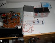
Been having another look at this and its quite interesting. I knocked up a pulse stretcher and this confirms that the data lines that appear to have no activity viewed on a scope actually do have occasional data present, and of extremely short duration.
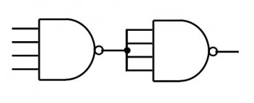
I can reliably detect when errors are occurring but I need a true AND function to check against the data sheet truth table. A couple of things are bugging me at the moment with this so it needs a bit of thinking through. I could only lay hands on a NAND 4 input gate... I know I can make a AND from NANDS... but something isn't quite right as it stands.
I can reliably detect when errors are occurring but I need a true AND function to check against the data sheet truth table. A couple of things are bugging me at the moment with this so it needs a bit of thinking through. I could only lay hands on a NAND 4 input gate... I know I can make a AND from NANDS... but something isn't quite right as it stands.
Attachments
Interesting view, considering the improvements in electronics and faster CDs and DVDs, I would have thought getting the data off the disc was reasonably mundane these days...
A good example is the CEM board shown earlier, from the CD player used, a single layer cheep as chips board, which even then was a less than optimal layout, never mind todays standards.
I'm paraphrasing what I read here. I personally dont know one way or the other. But, it does seem that dsp, algor, jitter, ec and the like have not been to the same standard from cheapest to top model. BenchMark ADC/DAC and others say jitter is the most likely problem being heard as differences. And, interfacing causes a lot of it. So, I need to go in that discussion direction soon.
IMO.
THx-RNMarsh
Last edited:
Too long wires at the input? 😉I could only lay hands on a NAND 4 input gate... I know I can make a AND from NANDS... but something isn't quite right as it stands.
Attachments
Yes, yes and yes. (I think 😀) It was a very long time ago sitting in a classroom at Sony with yard after yard of paper tape with representative 1's and 0's and showing how missing bits could be recalculated from the parity bits and check sums.
It surprises me not a little bit that you would know something about this. It wasn't you that the question was aimed at. I don't think some of these guys have a real appreciation of what is going on, or how powerful it is.
Parity bits and checksums are only a fraction of the armoury. Great for serial datacomms, but what about when you get a burst of hundreds of bits in error? You have to figure a way to distribute those errors among many bytes, otherwise they're just going to be missing or incorrect bytes.
That's what we do. Data is processed in blocks. The serial data is read into memory in contiguous blocks and processed so that no bit appears in the resultant bitstream in close physical proximity to the bits that flanked it in the original bitstream. This means that when it is written to disk, a burst error of numerous contiguous bits on the disk is shared across a large number of bytes. Now we can add redundancy to correct those errors when reading and re-arranging.
The operative word being correct.
This is a superficial description, which probably won't withstand detailed criticism in the light of the RB spec, but this is how you can have a huge chunk of data missing, but the EC can still recreate it.
It's kind of like a RAID drive array, but different obviously, but the same insofar as you can lose a whole drive, and just plug in another one and the system will recreate the contents.
Perfectly.
Eight-to-fourteen modulation - Wikipedia, the free encyclopedia
Reed?Solomon error correction - Wikipedia, the free encyclopedia
I don't think we should dig any deeper into it here. The system is robust and has been proved to work.
Reed?Solomon error correction - Wikipedia, the free encyclopedia
I don't think we should dig any deeper into it here. The system is robust and has been proved to work.
Last edited:
Does anybody remember any of this?
From what I recall, CDs will correct burst errors in the thousands of bits.
Hi,
Around 4K for CD audio.
CD-ROM does even better but I don't know the numbers.
rgds, sreten.
This means that when it is written to disk, a burst error of numerous contiguous bits on the disk is shared across a large number of bytes. Now we can add redundancy to correct those errors when reading and re-arranging.
Yeah that's interleaving... if you have a block code which can correct say, 10 bit errors on a block of 100 bits, just take 100 blocks, slice and interleave them, and if you get 1000 consecutive errors (say, a big scratch) then you get 100 blocks with 10 errors in each, and you can correct them. It increases latency and needs more buffers, so there is a limit to it.
Nice trick, 😉 ...So I mono'ed both y and z, and combined those into a stereo track, and listened to them binaurally, both forwards and in reverse (the latter to prevent getting caught up in the music and forgetting to listen for differences).
Good to hear ... these are always heart stopping moments when one first is made aware of such a situation - the house will live again ...I just got an email from a relative who says they are all OK. 🙂
But the house was completely leveled.
Thx
-Richard
Too long wires at the input? 😉
Hmmm... I think more a case of me trying to get my head around the problem.
We need to load the dice to try and see just the errors of interest and the last line of the truth table, all 1's just doesn't seem to occur even if you slow the disc manually until audio is lost.
I'll have a another play and see what gives.
Very interesting, Mooly. Sorry if I've missed it, but what is the player/chipset and is there a link to the schematic (or I'll try to find) ?We need to load the dice to try and see just the errors of interest and the last line of the truth table, all 1's just doesn't seem to occur even if you slow the disc manually until audio is lost.
I'll have a another play and see what gives.
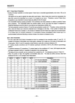
Edit : - ooops just found it in post #21, kindly ignore my Q. You prob know this but MNT0-3 are only valid on the falling edge of C4M, so need to use a register clocked by C4M neg edge to sample your AND circuit and arrange to latch and hold its output if MNT0-3 are ever all 1. I get what you say about MNT0-3 apparently never being all 1, but those states are transitory and not easy to see, hence the latch........?
This external visibility of EC should make for very interesting analysis, Mooly, good stuff.
Last edited:
Or use a counter, or use a scope triggered on the clock transition?
Inputting the output into a D ff clocked with the clock signal would work also of course.
Jan
Inputting the output into a D ff clocked with the clock signal would work also of course.
Jan
... In the field it varies by cost and related factors. ... It is interesting that the best transports and the best dsp et al happened a long time ago and has actually gone downhill afterwards. ...
I think you hit the target. Flagship implementations of new technology are usually well up the cost/performance curve. Then the race to the bottom begins... how cheap can we make it before it stops working? If the CD spec is so robust that even a poor drive will work, there's no incentive to make a good one.
I've had chance to have more of a look today... it all makes more sense when its in front of you and you can get a feel for what is happening however there is a puzzle.
Looking at the truth table and taking the data at face value we should see all error flags at logic 1 when a non correctable error is present. This is the last entry on the table. Using a four input NAND to detect this and feeding the output to a monostable shows this situation never occurs under any possible condition.
Also, I wondered at the meaning of the phrase 'uncorrectable error'. The first entry for this refers to the C1 data. So does that mean it is simply a non correctable C1 error that may be corrected by applying the C2 data and thus outputting a correct sample ? When we get to the last two entries in the table (both classed as uncorrectable) are we into the realm of substituting previous data samples and then moving toward average values of data for the final most severe uncorrectable sample/s.
Even with all this doubt there is still much that can learned from looking at the behaviour of the flags. One useful tool in addition to the monostable is a high brightness LED, a Cree device of the kind that burns your eyes out at 50 paces when fed from a couple of milliamps. The monostable shows the presence of a pulse or change of data but gives no clue as to how often this occurs. The LED comes into its own here. For example playing a 'perfect' disc it flickers very very dimly at around (guestimate) 5 to 10 random pulses a second. This is only present on the MNT0 line for 99% of the time, however monitoring the MN2 line shows a very occasional one off pulse. These must be true random errors form whatever reason.
I'm going to look at more detail at what happens when playing known defects (it all seems to behave as you would expect with the exception of the MNT3 flag)
Attachments
Just need to take care that the min pulse width nec to trigger the monostable is met, because strictly the condition is perhaps only valid for a very short time synchronous with C4M a 4MHz clock. Might only be valid to meet setup and hold of one c4M edge.........it's worth using a D-ff or J-K ff clocked from neg edge of C4M to either extend the condition to be at least one C4M period long (250nS), or some other arrangement to latch it. Sure you know but at 4MHz need to take a bit of care with layout and transmission of sigs, of course.Using a four input NAND to detect this and feeding the output to a monostable shows this situation never occurs under any possible condition.
I think there is a 'pointer' or flag for C1 and C2 errors, and a status flag for successful correction. The final two states represent pointers and flags for uncorrectable errors, the pointer happening first - but both will happen in sequence (being uncorrectable).Mooly said:Also, I wondered at the meaning of the phrase 'uncorrectable error'. The first entry for this refers to the C1 data. So does that mean it is simply a non correctable C1 error that may be corrected by applying the C2 data and thus outputting a correct sample ? When we get to the last two entries in the table (both classed as uncorrectable) are we into the realm of substituting previous data samples and then moving toward average values of data for the final most severe uncorrectable sample/s.
Go for it, very interesting.Mooly said:I'm going to look at more detail at what happens when playing known defects (it all seems to behave as you would expect with the exception of the MNT3 flag)
- Status
- Not open for further replies.
- Home
- Member Areas
- The Lounge
- CD Error Correction. Is it Audible ?