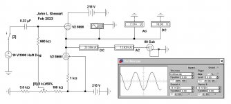
Here is what looks like a good start on that, Doesn't need to be 50 mA all the time, just on peaks,Note the peak grid current runs 50mA+/-. Can the dual-triode pass that much?
I'll try a larger signal later.
The EWB simulator was developed long after toobz were out of style. So no vacuum diodes.
But the workaround is no problem, simply cause a triode to think it is a diode.
Stuff in the required parameters & a good diode with 3/2 halves curve results,
This one looks like one plate of an 80, 125 mA at 60V.
In the sim the voltage on the diode has settled very close to the required on the 811 schematic.
EWB has problems with positive voltages on the grid with respect to the cathode.
See if I can come up with a work around later. 😀
Attachments
Your opinion. It was a starting point.What's the point of this thread
Some history for those with a short memory
The discussion of this 811A SE amplifier started in another thread. I’d started a thread to shew how I had determined the size of the resistance inserted between the output tubes & the loudspeaker load by the OPT. By the 4th page the subject of local NFB had been brought up as a way of reducing internal impedance of any amplifier. Several examples of commercial amps using CFB were given.
45 offered the 811A SE triode circuit he was familiar with. The discussion quickly became one of how 24W audio was possible as claimed by the originator.
The original purpose of the thread on OPT insertion loss was now completely off topic, it was time to start a new thread on covering CFB. I suggested that, but nothing happened. So I started a thread open to anyone’s example of CFB. The thread simply started with the 811A SE amp where the previous thread had progressed to. Otherwise the rest of the thread is nothing more than some of us asking other questions & finding answers, often in the history of toob circuit development.
Many hobbyist’s tend to relate to their build or project as an extension of themselves & view any criticism of it as an attack on themselves. Not a good position in a freewheeling discussion here on DIY. Or anywhere else.
Criticize the work, not the person.
JLS

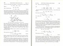
Refer to the paragraphs at the lower RHS. 25% efficiency is about the limit for common triodes. From Seely, published 1958. And used by many as I did.
If anyone here thinks they have a better solution than the Zeke's who developed this technology for us, speak up! 😀
If anyone here thinks they have a better solution than the Zeke's who developed this technology for us, speak up! 😀
Attachments
If the CFB was the real purpose then you would not start arguing again on the 811A amp. In fact that amp is a lot more than just CFB. It's as simple as that and you know it. Maybe if you build a real class A2 amp instead of proving something with simulations based on static, generic, average, low resolution curves you might realize such an output stage has the same efficiency of pentodes at the very least, if driven decently. This means up to 40% anode efficiency with the less conventional Shishido style inverted interstage transformer or more common basic DC-coupled cathode follower with resistive load. More efficiency if better performing cathode/source follower is used with devices that also have good gm of their own. Getting close to the max permissible of 50%....
25% is an average typical anode efficiency for class A1 triodes. I invited you to do a comparison between conventional triode and class A2 output stage using the 46 EXACTLY for this reason. Same device, 2 different ways to use it. In that case you only get up to 40% in class A2 with it as it really has low gm. Class A1 triode doesn't even reach 20%....
Among class A1 working triodes, the 300B already defies that RULE OF THUMB of 25% with typical efficiency of 30-35%. Is the latter a myth too?
Last edited:
I run my 845 amplifier with cathode feedback from the secondary. Using the 16 ohm tap gives you a bit of a bump in impedance that the tube sees. As far as I remember it pushes a 5K primary closer to 6K.
Been my daily driver since about 2015.
The 811 has a fairly high plate resistance to that bump in impedance could really help.
Back in my head banging days I ran 811As push pull with CFB from the 4 ohm tap. Sounded fairly good but changes in speaker tastes pushed me to lower power.
Been my daily driver since about 2015.
The 811 has a fairly high plate resistance to that bump in impedance could really help.
Back in my head banging days I ran 811As push pull with CFB from the 4 ohm tap. Sounded fairly good but changes in speaker tastes pushed me to lower power.
With a source-follower driver I've hit 45% efficiency with a VT-127A (an obscure 100T variant) and 42% with a 211. Those were both with less than 1% distortion at the measured "max power" output, and including OT losses.
If you allow for more distortion at the measurement (say, 5%) that will get you an even higher efficiency number. Maybe even above 50%.
The 50% max theoretical limit only applies to undistorted sine waves, which of course don't occur in real amplifiers. If we take the extreme case of square wave output it is easy to get well above 50%.
So 24W seems like a very high output for an 811A, but in reality it may just reflect the willingness of the tester to push the tube too far in pursuit of a number.
I'd be more interested in what power level the amp hits 1% and 5% and what it is doing at 1W.
Edit: not to mention we also have grid current going through the cathode winding in this case as well...
Last edited:
The 845 is a textbook triode, a winner right out of the box, 👍I run my 845 amplifier with cathode feedback from the secondary
http://www6.plala.or.jp/Michi/811a24wseamp_0812.htmlI'd be more interested in what power level the amp hits 1% and 5% and what it is doing at 1W.
1% at about 18W, 5% 24W. THD at 1W is 0.15% when no local feedback between the cathode follower output and the input is applied, 0.3% with 5 db of such fbk. The reason is that without fbk there is 2nd harmonic cancellation and that's is by far the dominant harmonic. However above 8W output the lower Zout of the cathode follower with local fbk shows the benefits.
Another variant rated at 20W (running the 811A about 10% less hot) with 2% THD with lower overall distortion at any level below 12-13W (only 0.056% at 1W) in comparison to the other one, using choke loaded cathode follower with 4P1L:
http://www6.plala.or.jp/Michi/4P1L 811A 8/Third version of the 811A amp.htm
Last edited:
With CFB, you should aim for steep, high gm tubes. TV tubes are great for this. I did some SE CFB schematics with PL82 and PL83 tubes, achieving an efficiency of 44% before clipping including OPT losses. You can also simulate this in LTSpice before doing your schematic, if you do find tube models.
With the 300B ( just a good selected Chinese type, nothing really fancy or expensive), run for example at 360V/70mA (bias at about -75V) and 4K OPT, I can get 7W at 1% THD without any fbk with several different driving stages. That's already more than 25% efficiency. 5% limit depends a lot on the driver and how it's coupled, it can be about 8.5 W (class A1 limit) with conventional RC coupling to over 10W (that's slightly driven into positive grid of course). In the latter case THD at 8.5W about 3% and that's already almost 34% anode efficiency.
GU50 is becoming to look very attractive.With CFB, you should aim for steep, high gm tubes.
Of course higher gm is an advantage but often comes at cost of something else. Most pentodes work really well with CFB between 10-20%.. I would say from 5-6 mA/V gm or more will be just fine. If the output power is not the main requirement, even one old favourite of mines, the 6F6, works great. With 10% CFB one gets a lovely 10W PP @1% THD class A amplifier.
You've talked a lot about Michi's amps. How about shewing us something of yours?With 10% CFB one gets a lovely 10W PP @1% THD class A amplifier.
Complete with performance data, how you did it & with what measurement equipment.
Lets see if you get the results you expect without the application of Cooke's Variable Constant.😀
That's not too out of line with my experiences. My circuit was pretty heavy local feedback (output tube plate to driver cathode) of up to 35dB or so. I didn't feel comfortable going past 1% distortion testing as I was getting huge sharp peaks in the power tube grid waveform as the feedback circuit tried to drive hard into saturation and cutoff to get more output. I didn't want to melt any grid wires.http://www6.plala.or.jp/Michi/811a24wseamp_0812.html
1% at about 18W, 5% 24W. THD at 1W is 0.15% when no local feedback between the cathode follower output and the input is applied, 0.3% with 5 db of such fbk. The reason is that without fbk there is 2nd harmonic cancellation and that's is by far the dominant harmonic. However above 8W output the lower Zout of the cathode follower with local fbk shows the benefits.
Another variant rated at 20W (running the 811A about 10% less hot) with 2% THD with lower overall distortion at any level below 12-13W (only 0.056% at 1W) in comparison to the other one, using choke loaded cathode follower with 4P1L:
http://www6.plala.or.jp/Michi/4P1L 811A 8/Third version of the 811A amp.htm
I operated the 211 with only a couple of volts of negative bias and that was the tube that gave me the lowest distortion (compared to several higher-mu transmitter triodes that required tens of volts of positive grid bias at idle and had higher mu). Crossing from negative to positive grid voltages throughout the cycle didn't seem to be a distortion problem at all. At least not with that tube.
Another tube, the VT-127A (basically a 100TL with extra leads and a 50W filament) generated high-order harmonics at all output levels. I tried all sorts of experiments in lowering grid driver Zout significantly to tame them and that made no difference. Swapping to a different sample of VT-127A made a huge difference though. The relative amplitudes of the high-order harmonics would all change from sample to sample. It's just something inherent to the type. The amplitudes of the high-order harmonics were tiny but none of the other tubes I experimented with had them.
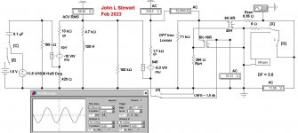
For the fans of the 845 & 10Y here is just that. I've assumed an efficiency of 85% for the OPT,
split between the iron & copper losses. All stuffed into the Sim. About 15,5 Watts of the signal get to the load in these conditions.
For the SE 845 in Class A all of the conditions listed on the data sheet shew efficiency of ~25%.
split between the iron & copper losses. All stuffed into the Sim. About 15,5 Watts of the signal get to the load in these conditions.
For the SE 845 in Class A all of the conditions listed on the data sheet shew efficiency of ~25%.
Attachments
I can but but really have no interest in arguing with you. I really do not care about Cooke's variable. Spreadspectrum maybe explained better what is also my point of view about REAL amplifiers which you seem to ignore. So what would be the point? I think I will never quote/comment any of your posts anymore. Really a waste of time from my perspective.You've talked a lot about Michi's amps. How about shewing us something of yours?
Complete with performance data, how you did it & with what measurement equipment.
Lets see if you get the results you expect without the application of Cooke's Variable Constant.😀
Does that mean you have no examples of your work in this field then???I can but but really have no interest in arguing with you. I really do not care about Cooke's variable. Spreadspectrum maybe explained better what is also my point of view about REAL amplifiers which you seem to ignore. So what would be the point? I think I will never quote/comment any of your posts anymore. Really a waste of time from my perspective.
I did not say that. I asked what would be the point.Does that mean you have no examples of your work in this field then???
You want to argue on what I would post using a WRONG model that ONLY applies to IDEAL class A1 amplifiers. I don't think you would change your attitude and consider both a realistic approach and that class A2 is DIFFERENT (and so your Cooke's model does not apply). You have been doing this ALL the time in this thread and the other one. I was about to post my results it in the other thread but when I saw this one I changed my mind because I realized it would have been a waste of time. I only replied in this one because you were slandering someone's else work with flawed calculations. Why didn't you evaluate the output power for the 46 in Class A1 triode and Class A2 as I asked? That is enough for everyone to understand how wrong you are.....
Last edited:
- Home
- Amplifiers
- Tubes / Valves
- Cathode Feedback from Output Transformer Secondary Free for All