It takes a really high mu (or is it high Gm?) output valve to have any significant cathode feedback from a normal speaker secondary winding. Even 3dB is tough to get to. OTOH, it's largely penalty free.
All good fortune,
Chris
All good fortune,
Chris

Chris, the 5K Tango with 36R CFB would generate approx. 2.5 dB feedback. In a 750V 15W amp, that already needs a driving voltage of about 190-200V p-p it would go up to about 260- 270V p-p (also taking into consideration that the cathode output has gain <1)! Not really penalty free, unless you already have a very good driver stage that can do that.
Yes, and I did specify a normal speaker secondary winding. 15 Watts at 8 Ohms is about 11 VRMS, not much.
All good fortune,
Chris
All good fortune,
Chris
f you built that one why don't you use that as an example? Shew us with some measurements & how you did that.With the 300B ( just a good selected Chinese type, nothing really fancy or expensive), run for example at 360V/70mA (bias at about -75V) and 4K OPT, I can get 7W at 1% THD without any fbk with several different driving stage
THX
CNFB on a Grand Scale, Clones of Norman Crowhurst's Twin Couple Amplifiers, the poor man's McIntosh.
Crowhurst authored three articles in the 50s covering his idea for Unity Coupling but avoiding the difficult to build McIntosh OPT.
He used two ordinary OPT, altho they had to be a special ratio not found in common OPTs. He had these wound for the project.
This scheme results in ~14 db local nfb. The output stage has a good DF before the application of overall nfb.
I built two of these for experimental purposes. My versions are all SS PS's. The first version has a soft start & is regulated
Plates are at 400V, the screen at 300V. The hookup is also part UL. The first amp uses PP 6LU8s.
The 6LU8 included triodes are CFs direct to the output grids, no blocking. The cct may be switched between Crowhurst's front end
& a full differential mode. The full loop nfb can be switched on or off. Those switches don't shew on the early schematics.
All of the parts are all off the shelf, no specially selected boutique parts at all. The amp clips at a little more than 30W.
And the resulting measurement results look real god. Without the use of Cooke's Variable Constant.
The first of these was published in AudioXpress magazine Aug 2004.👍
Attachments
-
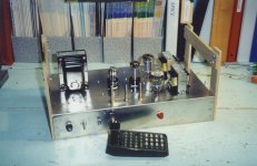 Twin Coupled Amp Front for RHS Veiwing.jpg195.6 KB · Views: 171
 -
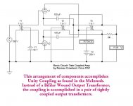 Crowhurst Twin Coupled Principle.jpg60.5 KB · Views: 138
 -
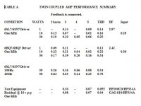 Table A Twin Coupled Amp Performance Summary.jpg42.8 KB · Views: 147
 -
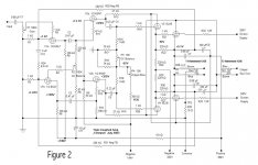 Twincoupled Amp D Nov6.jpg91 KB · Views: 144
 -
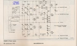 Figure 6 Power Supply Clone of Twin Coupled Amplifier w Caption.jpg213.4 KB · Views: 157
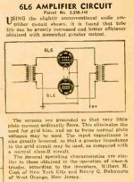
The 6N6G & several others like it are good examples of what Mr 45 has been talking about, but all in one bottle.
A pentode connected as a zero bias triode but forward biased into grid current by an enclosed triode CF.
This one plugs right into the same socket as a 6F6. 6K6, 6K6 & so on. And has the advantage of not requiring separate bias.
Triadyne did a lot of development on a series of these toobz. FlaCharlie has built a few amps based on these with good results. 👍
Attachments
For the curious & others here is some of the results of the work at Triadyne.
THX to FlaCharlie for bringing this work to our attention a while ago.
And the application of pentodes as zero bias triodes, G1 at zero & the screen driven.
That becomes a hi mu triode, probably well known in the lab during the development of the pentode.
NTL some folks still found a way to get the circuit patented, even tho it was probably already in use.
The US Patent Office in the past has sometimes been a free for all. And well known for that.
Attachments
-
6B5 Triadyne.pdf554.3 KB · Views: 92
-
6AC5G Triadyne.pdf77.9 KB · Views: 136
-
6N6MG Triadyne.pdf200.1 KB · Views: 78
-
25AC5GT-6AE5G Triadyne.pdf71.2 KB · Views: 71
-
 Gonset Class B Zero Bias Modulator.jpg57.8 KB · Views: 109
 -
 Patent for Zero Bias Operation of Pentodes with Grounded Screen.jpg62.2 KB · Views: 122
6F6 6SN7 Amplifier
About 20 yrs ago I was curious with regard to toobz such as the 6N6 but didn’t want to part with the $$$$. This was not going to be a major project. The easy way out was to ‘roll my own’ hi mu triode using an existing pentode. For that I used a 6F6, G1 & G2 driven by both sections of a 6SN7GT. All haywired together on the bench.
The resulting contraption worked pretty much as advertised. When the driver triode plate was connected to the B+ supply the composite tube looked like a pentode. When the driver plate was connected to the 6F6 plate, the composite tube looked like a triode. And when the triode plate was connected to the OPT CT, the composite tube became UL.
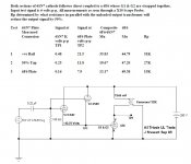
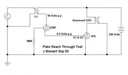
While on the bench I had a look at the inverted triode effect that Terman had described in the early 30’s. To do this I used a Hammond 447 IT so that an external audio generator could drive the plate of the driver triode. The measurement point was well off ground at B+ so I used a differential probe in front of the scope. A 20V signal on the driver plate resulted in 0.5V at its cathode, confirming that mu’ of the inverted triode is 1 /mu.
From the evidence we could conclude the plate of the driver triode performs the same function as the screen grid in an ordinary pentode.
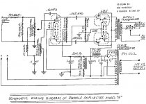
One commercially built amp using these kind of toobz is the Rockolab using PP 6B5s. If the amp had a UL OPT the driver plates of the 6B5s would be connected to the UL taps.
About 20 yrs ago I was curious with regard to toobz such as the 6N6 but didn’t want to part with the $$$$. This was not going to be a major project. The easy way out was to ‘roll my own’ hi mu triode using an existing pentode. For that I used a 6F6, G1 & G2 driven by both sections of a 6SN7GT. All haywired together on the bench.
The resulting contraption worked pretty much as advertised. When the driver triode plate was connected to the B+ supply the composite tube looked like a pentode. When the driver plate was connected to the 6F6 plate, the composite tube looked like a triode. And when the triode plate was connected to the OPT CT, the composite tube became UL.
While on the bench I had a look at the inverted triode effect that Terman had described in the early 30’s. To do this I used a Hammond 447 IT so that an external audio generator could drive the plate of the driver triode. The measurement point was well off ground at B+ so I used a differential probe in front of the scope. A 20V signal on the driver plate resulted in 0.5V at its cathode, confirming that mu’ of the inverted triode is 1 /mu.
From the evidence we could conclude the plate of the driver triode performs the same function as the screen grid in an ordinary pentode.
One commercially built amp using these kind of toobz is the Rockolab using PP 6B5s. If the amp had a UL OPT the driver plates of the 6B5s would be connected to the UL taps.
Attachments
So where am I going with all this, the last three posts? It appears obvious the zero bias triodes referenced in earlier threads
as a contenders in Class A audio may not follow the arguments offered. And that they defy gravity & several other knowns.
Looking at the circuitry all of the Zero Bias triodes need to be driven into positive grid current by some kind of auxiliary circuit.
To calc the real efficiency of the final tube, the power required to feed the driver cct must be added into that.
Now 48% efficiency looks a long way off.
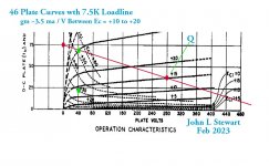
As Mr 45 requested I did a plot of a loadline on the 46 Class B curves, in this case 7.5K hinged at 280V & 37.5 mA.
A shade more than the 10W plate diss spec.
I used another 46 in Class A as the driver, when the 7.5K load is driven hard the 46 output section needs ~20 mA. Looks OK.
The audio output on the Sim looks like >4W. But it will be less, the plate curves on the RHS of the plate graph are nowhere as productive.
Unfortunately we don't have that data.
Make your own conclusions.😀
as a contenders in Class A audio may not follow the arguments offered. And that they defy gravity & several other knowns.
Looking at the circuitry all of the Zero Bias triodes need to be driven into positive grid current by some kind of auxiliary circuit.
To calc the real efficiency of the final tube, the power required to feed the driver cct must be added into that.
Now 48% efficiency looks a long way off.
As Mr 45 requested I did a plot of a loadline on the 46 Class B curves, in this case 7.5K hinged at 280V & 37.5 mA.
A shade more than the 10W plate diss spec.
I used another 46 in Class A as the driver, when the 7.5K load is driven hard the 46 output section needs ~20 mA. Looks OK.
The audio output on the Sim looks like >4W. But it will be less, the plate curves on the RHS of the plate graph are nowhere as productive.
Unfortunately we don't have that data.
Make your own conclusions.😀
Attachments

That last Sim is not yet the composite tube intended.
The LHS needs to be connected as a CF, its not.
Watch this space, Done tomorrow! 😀
👍
The LHS needs to be connected as a CF, its not.
Watch this space, Done tomorrow! 😀
👍
811A SE 24W Power Amplifier
I am honored to have my 811A single-ended amplifier from more than 20 years ago, which no longer exists, featured in this forum.
The amp mentioned above applies a positive bias (DC18.5V) to the output tube grid and always flows a DC current (13mA when there is no input). It is different from a normal negatively-biased single ended amplifier.
Due to the characteristics of the positive grid tubes, such as 811A, which are Hiμ and high rp, the effect of cathode-NFB was large, and the DF value increased from 0.2 to 2.0.
In the case of this amplifier, 47V AC voltage is applied at maximum output centered at 18.5V, and the grid current at maximum output increases further (18mA). Conversely, if the voltage is 0V or less in the negative direction, the grid current ceases flow. This causes an unbalanced +- waveform and secondary distortion.
For this reason, to deal with these problems, we adopted a 5998A cathode follower as a power drive tube with deep bias voltage and low impedance.
1) Transmitting tubes such as 811A can be used at 45 to 50W between CCS (45W) and ICAS (65W) without any problems, and I don't think it is necessary to be particular about 22W/24W output.
2) When the cathode NFB is applied, the load impedance of the output tube is: (root5000+root36) Squared=5880OHM as 45 mentioned.
3) If the CFB winding is not used, one end of either should be earthed as a treatment method.
4) In my current opinion, the cathode choke drive system is the best for sound quality reasons.
H.Michi
Mystery Solved
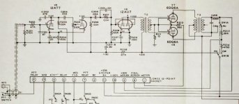
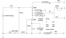
When the odd looking 5998 driver shewed up in this thread it appeared as something I’d worked on a couple of years ago. Searching thru a pile of thumb drives & scanning for EWB files I found what I’d been puzzling about, its attached here. I’d received a PM from a fellow in Australia in June 2021, I guess he had seen the results I was getting with PP 5998 amplifiers. That led to Michi’s website & others.
I say odd looking driver, not because the circuit arrangement is unknown, but the use of a 5998 in this configuration is. For the lurkers & newbies, a CF is very good at responding to a positive going signal but not so much when it goes negative. One easy fix is a cathode resister of higher value to a negative supply, say 100V. Even better in when there is another triode at the bottom, just like this cct using the 5998 twin triode. In that service the triodes are usually things like 6BQ7, 6BK7 & on & on.
So I had a look & concluded the bottom triode could easily be replaced by a resister resulting in a lot less complication. Bur many on DIY want something that looks impressive, so why not?
Attachments
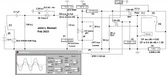
This one is where I got to with the analysis of the 46 46 vers, of a composite tube.
The small trace is at the load, the larger the drive to G1 of the 2nd 46.
A 1.5K resister accounts for the current required to drive G1 of the 2nd 46.
A better DF could be got by taking the NFB from a 16R tap on the OPT.
Without much of a stretch this technique could be used to analyze a G2 driven TV Horiz output tube so popular on DIY.
Attachments
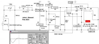
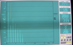
46 46 vers amp response to a step function.
The switches 'C' & 'Z' allow a step function on the amp front end.
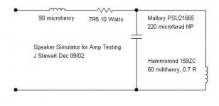
That red thing is a sub-circuit that contains a speaker simulator circuit.
The zero nfb response of this amp is reasonably good. How so??
The 46 rp at 20K is quite low compared to many common audio pentodes.
The rest of the damping is by the losses dialed into the OPT.
The switches 'C' & 'Z' allow a step function on the amp front end.
That red thing is a sub-circuit that contains a speaker simulator circuit.
The zero nfb response of this amp is reasonably good. How so??
The 46 rp at 20K is quite low compared to many common audio pentodes.
The rest of the damping is by the losses dialed into the OPT.
Attachments
EL34 >> 12-20KThe 46 rp at 20K is quite low compared to many common audio pentodes.
ECL/PCL82 >> 15-20K
EL86>> 23-26K
By the way, the 811a should be 6 mA/V and approx. 27K Rp at 600V/80-85mA.
The higher Rp the better but Gm is more important, IMHE.
If I were to build a 46 amp I would go for a 8W PSE with the more common 3.3-3.5K OPT used for 300B's. This way gm would be 2x. Individual cathode follower drive with signal split into 2 RC couplings from a single voltage amplifier. The 46 PSE with 3.5K OPT should provide about 5 dB CFB from the 8R secondary. If the distortion were 7-8% pentode-like at 8W output (I expect a bit less in the 5% region) such 5 dB CFB should make it equal or better than a 8W 300B SE without fbk anyway......
I happen to have a nice quad of NOS/NIB 46 Tung-Sol's and a nice pair of NP Acoustics NP3.5SE18F60 S (3.5K, 18W, 60KHz bandwidth) with amorphous core which I have been playing with until now in a 45 PSE. Actual copper resistance of primary of my OPTs is 120-121R, 0.25-0.26R for the 8R secondary. 21H minimum primary inductance (i.e. small signal). I might do it in the next months....

At which %THD are you measuring the maximum Wattage of the amps?
"Triodified pentodes" can easily overcome 25% and even 40% in A1.
I remember George of @Tubelab_com showing a table where he was always above 40% and most of the time above 45% of efficiency with a 5%THD.
Indeed with local feedback the pentodes achieve triode-like curves, but still having the g1=0 curve with the anode going down to around 40V.
This way it becomes easier to have pentode-like efficiencies with triode-like internal resistance and harmonics.
- Home
- Amplifiers
- Tubes / Valves
- Cathode Feedback from Output Transformer Secondary Free for All