A thread devoted to the subject of CFB from OPT secondary side to output tube cathode.
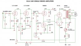
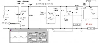
I've moved the 811 SE amp over here for a start. Looking at the operating conditions the claim of 24W audio doesn't make sense.
Running 80 mA plate current from a 600V supply looks like 48W plate dissipation, about the limit given in the RCA TT4 Transmitting Tube Manual.
In Class A Triode efficiency max's out at 25W. That can be pushed somewhat farther but it is no longer Class A & distortion increases.
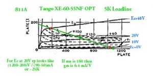
I tried plotting the Tango 5K loadline on a poorly copied image of 811 plate curves. Trying to flatten the RCA TT4 manual
to stuff into the scanner was a real problem, By using an olde formula found in many RCA tube manuals the loadline never got more than 12W.
I've included some very interesting links, some for the fans of transmitting toobz.
No Sim to measure DF yet, I'll stuff that into the thread later. Time to get outta here for a few hours, 👍
I've moved the 811 SE amp over here for a start. Looking at the operating conditions the claim of 24W audio doesn't make sense.
Running 80 mA plate current from a 600V supply looks like 48W plate dissipation, about the limit given in the RCA TT4 Transmitting Tube Manual.
In Class A Triode efficiency max's out at 25W. That can be pushed somewhat farther but it is no longer Class A & distortion increases.
I tried plotting the Tango 5K loadline on a poorly copied image of 811 plate curves. Trying to flatten the RCA TT4 manual
to stuff into the scanner was a real problem, By using an olde formula found in many RCA tube manuals the loadline never got more than 12W.
I've included some very interesting links, some for the fans of transmitting toobz.
No Sim to measure DF yet, I'll stuff that into the thread later. Time to get outta here for a few hours, 👍
Attachments
-
 811A 24W SE Amplifier.jpg85.3 KB · Views: 966
 -
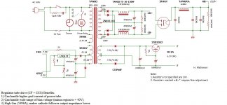 811A SE Amplifier PS.jpg106.7 KB · Views: 673
 -
 811A Plate Curves.jpg57.1 KB · Views: 455
 -
 Tango SE OPTs.jpg72.6 KB · Views: 350
 -
 811A Plate Curves & Power Limits A w Captions.jpg22.4 KB · Views: 335
 -
 Links to RCA & Other Documents.jpg93.6 KB · Views: 577

Hard to get a good result on those low resolution average curves. It's a highly inaccurate method. Anyway the effective load when CFB is used is about 5.9K (5K is at the plate and the rest at the cathode....Crowhurst used to called this partial cathode follower) and the tube curves are significantly more linear with CFB. In this case the CFB winding handles about 8% of the output signal which is a lot more than little CFB one can normally get using the secondary in a symmetric fashion. The title says 24W but in reality it's 22W at 5% THD. Not really a significant difference. There is no reason to doubt....
Last edited:
Is there a reason for the input swing to stop at +40V? Looks like you easily could get another 100V or so of plate swing by pushing the grid harder.
In fact one can estimate it gets to +42-43V. The driver passes 47V rms which is 66.5V peak. About 42.5 V go to the cathode and the remaining 24 V (starting from +18.5V) are amplified through to the plate. Also the 5.9K load is a bit flatter and getting to the knee for max efficiency.
The main reason to avoid going too deep is actually dictated from the other side where the grid goes from positive to negative (this time). Now matter how low is the Rout of the driver and its capability there will always be a characteristic pattern of distortion: after a few volts, say 5-7V with typical low mu DHTs, crossing the 0V point (both from negative to positive and vice versa) there will be a plateau in THD figure (or it might even slightly decrease a bit) and then sharply rise. Sure, an ultra low Rout of the driver will help but will not remove this feature. More importantly the spectrum of distortion shows a sharp change in content. The 2nd harmonic decreases a lot and the 3rd becomes the dominant. All other higher harmonics increase too. This explains why there is a plateau in THD, as normally the 2nd harmonic is the dominant one. The only way to get low THD is then to employ feedback, significant amount which is only doable with a loop more or less local. Still, the composition of the spectrum won't be the typical one. Maybe there is some rare exception but I haven't seen it, yet.Is there a reason for the input swing to stop at +40V? Looks like you easily could get another 100V or so of plate swing by pushing the grid harder.
So, one of the design requirement for that 811A amp is to stay always in positive grid field and eventually cross the 0V line only nearby the clipping. I generally do the same with traditional Class A1 or AB1 amps and only consider modest drive into positive grid field. This is also one reason why I rarely use a source follower in place of (higher Rout) cathode follower.
Last edited:
The Sim here gets a DF of more than 2 from the 811A. Still need to get a better estimate of the 811A rp & gm.
Maybe tomorrow, the new curves for it I posted earlier will help a lot. I don;t expect the end result will change much.
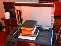
I've stuffed in a photo of the book flattening process trying to get a clean image of the 811A plate curves,
The Electronic Workbench Simulator has no transformer multiple secondary models, but the work around is not difficult.
Just another transformer with the primaries in parallel. The 2nd transformer ratio is simply varied to get the required NFB.
In this Sim of the circuit the 811A is simply driven either by the OPT voice coil winding or a tertiary wdg.
The Link to Radio Museum will take to a Cornucopia of magazines & publication from the past, in some cases to the 20s & 30s,
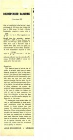
You can get your own personal copy of the Speaker Damping article in Audio Technology Magazine from Nov 1950 complete with
samples of typical test equipment of the era. And prices. 😀
👍
Maybe tomorrow, the new curves for it I posted earlier will help a lot. I don;t expect the end result will change much.
I've stuffed in a photo of the book flattening process trying to get a clean image of the 811A plate curves,
The Electronic Workbench Simulator has no transformer multiple secondary models, but the work around is not difficult.
Just another transformer with the primaries in parallel. The 2nd transformer ratio is simply varied to get the required NFB.
In this Sim of the circuit the 811A is simply driven either by the OPT voice coil winding or a tertiary wdg.
The Link to Radio Museum will take to a Cornucopia of magazines & publication from the past, in some cases to the 20s & 30s,
You can get your own personal copy of the Speaker Damping article in Audio Technology Magazine from Nov 1950 complete with
samples of typical test equipment of the era. And prices. 😀
👍
Attachments

There is a new clean copy of the 811A plate curves in post #1.So, one of the design requirement for that 811A amp is to stay always in positive grid field and eventually cross the 0V line only nearby the clipping. I generally do the same with traditional Class A1 or AB1 amps and only consider modest drive into positive grid field. This is also one reason why I rarely use a source follower in place of (higher Rout) cathode follower.
Shew how how would calculate what you've told us in your post.
Find 22 Watts. And shew us how you got a 5,9K loadline. THX 👍
You don't need to consider the CFB winding as a secondary. Rather it's a fraction of the primary so that the primary load is distributed between anode and cathode. Only this way you can achieve perfect geometry. At least in theory....
Often it is represented as a secondary winding but it doesn't need to be. Or better, one might see it like that if it were intended as an accessory winding. When I want CFB in my OPT I just consider it and get it done as fraction of the primary with much better results in all aspects.
Often it is represented as a secondary winding but it doesn't need to be. Or better, one might see it like that if it were intended as an accessory winding. When I want CFB in my OPT I just consider it and get it done as fraction of the primary with much better results in all aspects.
Last edited:
You have 25:1 plate ratio and 36R CBF. The CFB winding is loading the primary, not the secondary so 36R:8R means 2.1213:1 ratio. The total step-down ratio is (25+2.1213):1. and so for 8R secondary load you get 5884Rt total primary load. The rest of the calculation I have already done it earlier.There is a new clean copy of the 811A plate curves in post #1.
Shew how how would calculate what you've told us in your post.
Find 22 Watts. And shew us how you got a 5,9K loadline. THX 👍
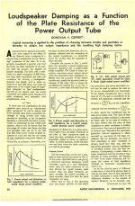
The way I see it is described in Fig16. In this case it's PP with tetrode, it's technically an ultralinear connection but the same maths can be applied to anything.
Note how (table 1) the output resistance is not really a measure of the behavior of the amplifier into a variable load. For example the PP triode with cathode bias (which has been chosen to work in Class A) has definitely a better damping factor respect to the Class AB Triode with fixed bias but the latter has better efficiency, lower distortion and is a lot less susceptible to load variations, in comparison. Although the 5881/6L6 is more like a worse case scenario (higher gm pentodes behave a lot better when triode-strapped), it shows the modified ultrlianear is the best practical option. In this example the amount of CFB is quite a lot but even with lower amount, it is still PRATICALLY the best option with pentodes/tetriodes in my experience and it really works/sounds great without the need of GRND fbk.
For the 811A amplifier: 2.1213/27.1213= 7.82% of the output signal is developed at the cathode and 92.18% at the plate. This percentage way of thinking is simply the most conveninet for me. It represents the partition of turns and so also the voltage partition. The feedback factor, the driver's swing and all relevant info are derived quick and easy.
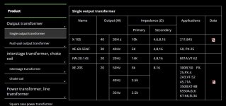
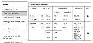
A transformer manufacturer has a little different perspective. The Tango XE60-SNF is a fairly big, general use 5K transformer. It will also work great in a 300B SE amplifier or 750V plate voltage 845 SE amp where using the CFB might not be convenient at all. Hence the CFB winding is presented in a different way (i.e. as an accessory winding that the user might leave unused). One could still use it as plate load (connecting the CFB in series the plate primary load with the correct PHASE) but in practice, this really depends on how it's been designed....
Note how (table 1) the output resistance is not really a measure of the behavior of the amplifier into a variable load. For example the PP triode with cathode bias (which has been chosen to work in Class A) has definitely a better damping factor respect to the Class AB Triode with fixed bias but the latter has better efficiency, lower distortion and is a lot less susceptible to load variations, in comparison. Although the 5881/6L6 is more like a worse case scenario (higher gm pentodes behave a lot better when triode-strapped), it shows the modified ultrlianear is the best practical option. In this example the amount of CFB is quite a lot but even with lower amount, it is still PRATICALLY the best option with pentodes/tetriodes in my experience and it really works/sounds great without the need of GRND fbk.
For the 811A amplifier: 2.1213/27.1213= 7.82% of the output signal is developed at the cathode and 92.18% at the plate. This percentage way of thinking is simply the most conveninet for me. It represents the partition of turns and so also the voltage partition. The feedback factor, the driver's swing and all relevant info are derived quick and easy.
A transformer manufacturer has a little different perspective. The Tango XE60-SNF is a fairly big, general use 5K transformer. It will also work great in a 300B SE amplifier or 750V plate voltage 845 SE amp where using the CFB might not be convenient at all. Hence the CFB winding is presented in a different way (i.e. as an accessory winding that the user might leave unused). One could still use it as plate load (connecting the CFB in series the plate primary load with the correct PHASE) but in practice, this really depends on how it's been designed....
Attachments
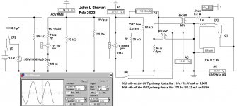
Here is what the load reflected to the power tube looks like, something 45 has referred to.👍
I've changed some of the values in the sim, it had started out as a continuation of the EL152 thread, Fixed now.
Driving the 811 with 40v p-p manages just over 13 Watts
But using these kinds of active components for the triode & pentode are perfect.
The 811 has quite a bit of curvature in its plate family. OK in a PP Zero Bias Class B stage for a modulator or public address
And Class C in a transmitter. But lots of inherent D% for use in an audio quality app. 😱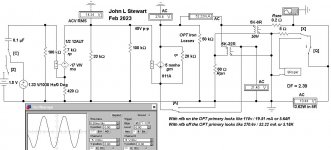
Attachments
Where does it say 24W? Some picture on the internet?the claim of 24W audio doesn't make sense.
Test results?
I get 16 Watts unclipped sine. (Not far from Svetlana's claims for low-Mu 811 variants.)
Note the peak grid current runs 50mA+/-. Can the dual-triode pass that much?
http://www6.plala.or.jp/Michi/811a24wseamp_0812.html
The actual driving voltage is 47 V rms or 133V peak to peak around +18.5 V bias point: about 48V peak to peak for the plate output and the rest goes to the cathode output.
The DC grid current is 13 mA in quiescent conditions and 18 mA at full power.
The actual driving voltage is 47 V rms or 133V peak to peak around +18.5 V bias point: about 48V peak to peak for the plate output and the rest goes to the cathode output.
The DC grid current is 13 mA in quiescent conditions and 18 mA at full power.
20W with the 4P1L driver: http://www6.plala.or.jp/Michi/4P1L 811A 8/Third version of the 811A amp.htm
24W with Cetron 811A and 22W with the RCA (which is the final choice, I think).Where does it say 24W? Some picture on the internet?
I disagree. The 811a published curves do not give accurate results. They are really low resolution. Try with the type 46 maybe you get better results, although I have always found that drawing load lines has never been accurate especially regarding distortion. It's only good for gross estimate. Anyway, with the 46 try 200V plate voltage, 50 mA (approx. +20V bias), 3K primary load and 41-42V peak to peak drive. You should get something between 3.5 and 4W output with the same distortion levels of standard Class A1 low mu triodes (around the typical 5%-10% THD). To get 3.5-4W from the 46 in triode connection with negative bias you need 2 of them in parallel, about 2X driving voltage and drive them for few volts into positive grid field. Once you add about 6-8 dB CFB to the Class A2 amp distortion will be significantly lower than the standard PSE. Of course the driver will need to be a bit beefier but nothing really challenging and likely less expensive as you save one power tube.But lots of inherent D% for use in an audio quality app. 😱
https://frank.pocnet.net/sheets/021/4/46.pdf
Last edited:
Picture here & it sez 24W, Each or together 24W?Where does it say 24W? Some picture on the internet?
http://www6.plala.or.jp/Michi/811a24wseamp_0812.html
Really don't understand why you took this amplifier as example of CFB if you don't believe the results. You keep doing even basic calculations wrong. Is that on purpose? For example, the swing you apply has been wrong all along. Worse, you have very little knowledge/experience of how it works, starting from the basics of output transformer, and yet you think you know what is true and what is not. What's the point of this thread?
- Home
- Amplifiers
- Tubes / Valves
- Cathode Feedback from Output Transformer Secondary Free for All