Don't rely too much on names.
From technical point of view I think it has only two technical names:
6th order Band Pass parallel (6P6P) or Compound Horn.
All the other names are non technical and are used to refer more to a specific layout.
Compare the Manifold / Devastator / Skram, they are the same type of enclosure, but different layouts.
Layout are important to fine tune the output for a specific drivers.
In terms of hierarchy, I would suggest to choose first the enclosure type based on technical names (family) in this case you are selecting the type of output you need (slopes, bandwidth, overall SPL), the second step is to choose the layout (individual part of the family), in this case you are optimizing based on the driver you have and the size ratios you need.

They lower acoustical impedance thus raising efficiency through the use of a resonance. Wall angle and terminus size effect directivity.How do horns and ported chambers work if they are the same thing?
You can place a flair and roll over on a Helmholtz or Quarterwave resonator.
Thanks 🙂They lower acoustical impedance thus raising efficiency through the use of a resonance. Wall angle and terminus size effect directivity.
You can place a flair and roll over on a Helmholtz or Quarterwave resonator.
So when you said “I’m new, help” you meant new to this thread and not to speaker building. Got it.
I agree that they both raise efficiency.
To my knowledge, they do it via two different types of resonance. If I build a sub with a 10cm long port, it will resonate quater waves at ~850hz. Well outside of the bandwidth I am using. However the 10cm long port can still be tuned to resonate 40hz with the right chamber and port area, via the Helmholtz resonance.
You can probably build an enclosure that combines both effects. A band pass horn for example.
This is how I understand it and it works when I model things. But I am not a professional and I could be wrong and I am happy to change my mind if someone can show me compelling evidence.
Take any front loaded horn sub. Model it in hornresp. Make the wall angle smaller to reduce the size of the mouth. Watch the efficiency fall dramatically.Wall angle and terminus size effect directivity.
I think most people would associate a manifold enclosure as an infinite baffle enclosure. However, I can see how a PPSL or a 2 driver BP4/BP6P could fall under the manifold type.I am new, help me..... What is a manifold? That slot?
Hofmann's Iron Law...efficiency, low, small...pick 2.Compromised Air Flow =lower efficiency
Positive flare = big & efficient.
Negative flare = small & low.
Straight flare = easy build, no angles.
My FriendPositive flare = big & efficient.
Negative flare = small & low.
Straight flare = easy build, no angles.
the flares still puzzle me, can you post some examples of negative VS positive VS straight
any sketch will suffice.
there are stuff that still do not compute on my old brain 🙂
If the positive Flare is tuned higher than its not bigger than the negative flared much lower tuned ?Hofmann's Iron Law...efficiency, low, small...pick 2.
Positive flare = big & efficient.
Negative flare = small & low.
Straight flare = easy build, no angles.
Is the positive flare ‘efficient’ because it’s big, or because it’s tuned higher?
Most people familiar with "Manifold Technology™" as we knew it back in the early 1980s when Electro-Voice popularized (and trademarked) the usage with speaker enclosures would not associate it with an infinite baffle enclosure, unless it happened to use multiple drivers on a manifold.I think most people would associate a manifold enclosure as an infinite baffle enclosure.
https://electrovoice.com/media/downloads/ev_pabible-18-add17-manifold_technology-1987.pdf
As usual with marketing terms, EV put a name on a technology that had been around for decades prior, similar to the introduction of the term "Tapped Horn".
Art
My Friend
the flares still puzzle me, can you post some examples of negative VS positive VS straight
any sketch will suffice.
there are stuff that still do not compute on my old brain 🙂
I'm using the driver inputs from post #124.
I made it simple. I flipped the throat and mouth between the 2 models.
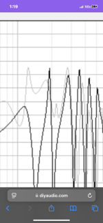
11ft Positive Flare TH with 4"x16" throat and 16"x16" mouth = 30.51hz tune = efficient & big.
7ft Negative Flare TH with 16"x16" throat and 4"x16" mouth = 28.00hz tune = low & small.
@BP1Fanatic this is a great comparison!
Now, I wonder why the negative flare has such a drastically saggy response in between the two resonances while the positive flare fills all that in very nicely?
I guess the ‘horn loading’ of the small cross-sectional area in front of the driver favors It’s TS parameters instead of that gigantic space in the tapered 1/4 wave pipe?
I also wonder why that little resonance blip appear in between the larger resonaces that formerly was a cancelation/full wave length multiple of the tapered tube?
Probably my number pattern/wavelength/harmonic psychosis again 🙈😝 but just a ‘math’ question actually?
Horn response recognizes the length and shape of the ‘cone’ instead of ‘pipe’ (or tapered pipes actual length) and some of those resonances fill in coincidentally at similar intervals ‘in between’ the odd numbered resonances of the tapered pipe?
Attachments
Last edited:
@BP1Fanatic
Now, I wonder why the negative flare has such a drastically saggy response in between the two resonances while the positive flare fills all that in very nicely?
I guess the ‘horn loading’ of the small cross-sectional area in front of the driver favors It’s TS parameters instead of that gigantic space in the tapered 1/4 wave pipe?
Tom Danley could probably answer those questions.
I would just make the negative flare TH longer for HT use.
YOUR magical 10 footer = 316L & 20.15hz tune.
It's still smaller than the 348L positive flare TH.
Maybe the tapered tubes and big bass reflex shapes function ‘better’ with a driver with the weaker motors and higher Qes ?
I would probably use a weak motor high Q driver in a BP4 for car audio.
do you still have the cabinets open or you already closed themI tuned mine to work best with four cabs v-plated. If I only planned on making one, or wasn't into v-plating, I would have made it slightly different
Here is the sketchup plan and cutsheet:
https://app.sketchup.com/share/tc/n...DLD8LDyiNw7KDszycRMhEXp2KghdNamZKP&source=web
i think you need to add some bracing where i draw the red lines
the area is too big and nothing reinforce the panel
so it might flex as it is directly in front of the driver
also i cant DL the model, you pasted just a see and browse link
- Home
- Loudspeakers
- Subwoofers
- Case for Discussion - Would a Single driver Manifold/MTB be better than Tapped Horn?