
@Potentiallyincorrect, now that I made some progress, I want to be sure I’m not going take 2 steps backwards again. Therefore, I’ll ask before that I’m ok Isolating power to those boards as you suggested and powering up the unit should be ok, correct?
Nothing is ever for sure, but from my review of the schematics the steps I outlined should still be ok to follow. They are what I would do were it my amp. If you can disconnect plugs where I indicated wires that would be preferred over unsoldering individual wires. I really can’t tell how the interconnect is physically accomplished from what I have. Do the minimum of disrupting things to isolate power to the boards in question.
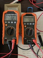
@Potentiallyincorrect Today has been extremely productive. Maybe because it started out on a positive note. I removed the plug that feeds board FEQ508 and boom, all my +/-16 volt rails came up to acceptable ranges -15.11/+16.1 on the Zeners 606 & 607. I started probing some of the points genrose had me check like at R510 which was +11.82vdc is now +16.2vdc and R522 was -9.69v is now -15.1. For the hell of it I jumped on the bias points and actually had to drive the bias down to get to 5mv. I brought it down even lower until we remedy the issue to 2.5mv. I’m charged up now, what’s next lol
I’ve attached a picture of my left and right bias settings without FEQ508 in the circuit
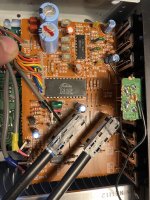
Also traced the wires to the trouble board and included s as picture of it as well
I’ve attached a picture of my left and right bias settings without FEQ508 in the circuit
Also traced the wires to the trouble board and included s as picture of it as well
Attachments
Last edited:
Ok, big progress.
I would plug the FEQ board back in and look for the hot or atypically warm IC. It looks like there is one dual and one quad op amp package. In addition to those there is IC802. That is an analog switch / multiplexer in a 24 pin package. Unfortunately my blind guess is that is likely the culprit. The rationale for that is that it has direct exposure to the receiver RCA inputs. Just guessing that there was an ESD hit when plugging unplugging cables. Its unfortunate as being a 24 pin package it would be the most difficult to replace and may be difficult to source.
IF my suspicion is correct, we could hope to see an out of place voltage on one of those RCA jacks. I would probe them as an additional debug step that is simple and could help zero in on which IC (or other component) is at fault.
Report back with your observations and we can formulate what's next.
So I made the voltage checks last night and this is what I have. Thoughts?
phono in
L 4.8mv
R 4.7mv
Video/Dad
L .5mv
R .2mv
Aux
L mv
R .1mv
Tape in 1 Tape out 1
L 0mv. L 5.4mv
R 0mv. R 5.3
Tape out 1 Tape out 2
L 0mv L 5.5mv
R 0mv R 5.2mv
phono in
L 4.8mv
R 4.7mv
Video/Dad
L .5mv
R .2mv
Aux
L mv
R .1mv
Tape in 1 Tape out 1
L 0mv. L 5.4mv
R 0mv. R 5.3
Tape out 1 Tape out 2
L 0mv L 5.5mv
R 0mv R 5.2mv
I was hoping we get lucky, no such luck as all those voltages are very close to zero. Anything feel warmer than might seem normal? That IC802 should not generate any heat.
I did not notice any excessive heat at all. I’ll bring in my infrared thermometer later but I think they seem normal by finger touch
@Potentiallyincorrect, I may have gotten somewhere or perhaps gotten nowhere but this is what I did and think I stumbled on. So I was studying the diagram and it looked like 2 of the easier terminals to unsolder power to would be terminals 4 and 11 on IC801. It also looked to me like that is an op amp for phono. Anyways, I unsolered terminals 4 & 11 and kaboom, voltages are up substantially, still less on the - 16 rail but is at -12.56vdc and the other side is +15.81vdc. i am able to adjust bias again as well. If that IC is bad, it looks like I can get one from online components and I’ll check mouser and digikey as well. Thoughts?
It can’t hurt, if you are careful. That negative supply should have responded better. You reduced the load, by disconnecting, but it might not be the problem load. Another thing you can do is run audio through all the RCA inputs and listen for abnormal response.
Ok, I will do that. I tested Video/DAD, Aux but not video in 1 &2 earlier. It was playing like a raped ape. I’ll test the others later. Probably no point in checking phono with that IC801 chip out of the circuit?
Ok, one last debug step B4 we just start replacing IC's. There is a 100 Ohm resistor connected to pin 12 of IC802 (R828? hard to read on my schematic). We can use it to measure the VSS2 current of IC802. That IC pin should nominally draw 1 with a max of 3 mA. Given that I would expect the DC voltage drop across this resistor to be less than 300 mV. If its significantly greater than that, IC802 would be considered bad. There aren't any electrolytic capacitors across the +/- 16 volt supplies on this board, so with the exception of the 3 IC's there aren't any other likely causes for the excessive current to explore.
Good luck and let us know how it turns out when you can get to it.
Good luck and let us know how it turns out when you can get to it.
I will definitely check that out. I did something else last night, I reconnected IC 801’s power terminals and unsoldered terminals 4+8 on IC 803. That op amp looks to me like it mainly affects the preamplifier section. Not that this means anything at all, I checked my voltage again to FEQ-508 and they jumped up on both rails to above +/-14vdc. Alright I do realize I have dropped off the load again, it was interesting that both legs of power we’re almost the same but still lower than +/- 16vdc. Just thought I’d share
@Potentiallyincorrect, it’s been a crazy week. I didn’t want to leave you hanging. I will get to this check this weekend. Any thoughts on the +/-16v rails coming up to over +/14vdc or is that just because I removed some load and non issue?
@Potentiallyincorrect, I checked the voltage drop across R828 and I have .4mv’s with IC801 & IC853 back in the circuit. It seems like the voltages really take a dive when I power up that IC853? That is the one that deals with the preamp boards. Thoughts?
This may be a something or possibly a nothing but I measure all of the pins of IC802. A couple of them really jumped out, number 22 in particular. I’m listing the voltages of what I measured vs what they should be on the pins of the chip. Here are the measurements:
T1. 1.2mv, should be 0
T2. +10.77 should be +16v
T3. +60mv should be .1
T4. 1.mv should be 0
T5. 1.2mv should be 0
T6. 4.9mv should be 0
T7. 4.8mv should be 0
T8. 0v should be 0
T9. .2v should be 0
T10. .1v should be 0
11. 5.1v should be 0
T12. -8.52v should be -16v
T13. 5.5mv should be 0
T14. .1v should be 0
T15. .3v should be 0
T16. .3v should be 0
T17 5.5mv should be 0
T18. 5.5mv should be 0
T19. 1.3mv should be 0
T20. 1.3mv should be 0
T21. 1.3mv should be 0
T22. +9.61v should be 0
T23. 1.5mv should be 0
T24. +10.15 should be +16v
Any thoughts?
- Home
- Amplifiers
- Solid State
- Carver MXR-130 Bias help!