Sometimes like @genrose said previously, its better to restart. I got home last night and second guessed working on this thing and should’ve waited until the morning. With that being said, disregard my comment about the resistor values. They are correct. I was looking at the values for resistors R555 & R557 which are the lower values instead of R655 & R657. One manual looking at R555/R557 and the other manual looking at R655/R657 smdh. Sorry about that.
@Potentiallyincorrect, When you say to pull a cap and measure corresponding for +/-16v, are you referring to resistors R510 & R522 or somewhere else in the circuit? Thanks you in advance
No, remove C623 temporarily. If its the cap, the negative supply currently measuring about -9.7 volts will after the pull read about -16 volts.
Ok gotcha, that’s what I did. This is what I have after removing C622. On the anode of zd607 my voltage didn’t change at all. I’m reading -9.57vdc and on the cathode of zd606 I’m reading positive +11.77vdc. Prior to powering up this morning, R655 which is a 680ohm resistor measured 900 in the circuit and R657 which’s value is 820 ohms measured 555 ohms in Ckt prior to removing cap. Tested Cap C622 which’s value is 470uf and it measures 472uf. It’s good but I do have a new on hand to replace it with due to its age. What I’m finding and I don’t know if this is normal, on one side of R655 I measure +40.27vdc and the other side I read +11.26. On on side of R657, I measure -40.5volts and across it I measure -9.58vdc.
notess
No, remove C623 temporarily. If its the cap, the negative supply currently measuring about -9.7 volts will after the pull read about -
take those resistors (655 & 657) out completely or lift one end and measure them... dont measure them in circuitOk gotcha, that’s what I did. This is what I have after removing C622. On the anode of zd607 my voltage didn’t change at all. I’m reading -9.57vdc and on the cathode of zd606 I’m reading positive +11.77vdc. Prior to powering up this morning, R655 which is a 680ohm resistor measured 900 in the circuit and R657 which’s value is 820 ohms measured 555 ohms in Ckt prior to removing cap. Tested Cap C622 which’s value is 470uf and it measures 472uf. It’s good but I do have a new on hand to replace it with due to its age. What I’m finding and I don’t know if this is normal, on one side of R655 I measure +40.27vdc and the other side I read +11.26. On on side of R657, I measure -40.5volts and across it I measure -9.58vdc.
At the risk of jumping to conclusions, it's looking more and more like one or both of the op amps has gone high current. The current through both of those resistors is close to equal (40 ma). The unequal measured voltages is likely due to the differences in resistor values (820 vs 680). The currents being mostly equal and excessive points to a current flowing through the op amp(s) and does not point to being diverted through another component. A high current op amp would explain everything.
Hi luvrockin,
Don't go changing anything yet.
I'm coming in late to this, but I was authorized warranty for Carver and worked on these units.
Can you please tell me what the current state this set is in? Do you have proper bias currents, DC offsets? Are your 16 V rails where they should be? The resistors you are talking about can go up in value due to heat over time. If this has happened, put the same value in, but with a higher power rating. I normally use metal film or wire wound resistors. Dale makes some nice 3W wire wound units.
Be very careful with these units. Make certain your main supply voltages are correct for starters. Then make certain your output collectors are sitting at the lower supply rail, not the high rail. Once these checks have passed you can start looking deeper. Set the bias controls at the lower setting in case you solve a problem and the bias current returns to normal.
The biggest issue with these are the speaker relays going intermittent. There are other things to deal with, but they need a Carver technician to solve. Be aware that these are a little different than a normal amplifier, and you can also run into a situation where you get excessive current flow in the output stage if the bias is knocked high, resulting in very high dissipation and quick destruction. Also, the dim bulb tester is exactly wrong for these, it may cause the triac to conduct over a large conduction angle and cause damage. The lower the supply voltage, the more current these will draw and that can totally confuse you. There is a "soft start" procedure a Carver tech knows how to do, and it is dangerous for an untrained tech, never mind a hobbyist to attempt.
If the power regulator is damaged or shorted, your supply voltages can reach extremely high levels and cause destruction all over the place. The supply voltages are regulated in these sets, which is why this is test #1 every single time you begin looking at one.
-Chris
@Potentiallyincorrect, is there a process?
@anatech, I bought the unit off eBay for dirt cheap. I use to own a Carver receiver as a kid. I thought it was the MXR130 but once I received it, I realized I had the MXR2000. Oh well, I wanted a toy to tinker with and if I get it going, I’ll eventually bring it to my system and see how it sounds compared to some of my other equipment. When I received it, I opened up the top of the unit and visually inspected it. Other than some really hacked solder joints, I didn’t see anything burned up so I plugged it into a dim bulb tester and powered it up, which you mentioned is not correct. Nothing smoked or sounded weird. I removed it from the dim bulb and went to straight power. I connected up a source and some test speakers. It works, and it plays fine. I found the service manual online and looked at some of the known issues with these things, the alignment process and some of the known issues for failure. I addressed a lot of the solder joints that looked shotty, replaced the output relays along with beefing up some various resistors, those you mentioned up to 5w with exact values. The voltage adjustment is exactly at 61v on d626 (cathode to chassis.) The idling voltage is where I’m having the issue. The Service Manual calls for 5mv on test points 602 & 601 for the left channel and test points 603 & 604 on the right channel. The bias is only .2mv on the left channel and .3mv on the right. I tried to adjust SVR 501 for the left & SVR 502 for the right channel. The highest I can bring the bias is up to .6mv on the right channel and .4mv on the right. Any help would be greatly appreciated. Thank you in advance, Joe
@anatech, I bought the unit off eBay for dirt cheap. I use to own a Carver receiver as a kid. I thought it was the MXR130 but once I received it, I realized I had the MXR2000. Oh well, I wanted a toy to tinker with and if I get it going, I’ll eventually bring it to my system and see how it sounds compared to some of my other equipment. When I received it, I opened up the top of the unit and visually inspected it. Other than some really hacked solder joints, I didn’t see anything burned up so I plugged it into a dim bulb tester and powered it up, which you mentioned is not correct. Nothing smoked or sounded weird. I removed it from the dim bulb and went to straight power. I connected up a source and some test speakers. It works, and it plays fine. I found the service manual online and looked at some of the known issues with these things, the alignment process and some of the known issues for failure. I addressed a lot of the solder joints that looked shotty, replaced the output relays along with beefing up some various resistors, those you mentioned up to 5w with exact values. The voltage adjustment is exactly at 61v on d626 (cathode to chassis.) The idling voltage is where I’m having the issue. The Service Manual calls for 5mv on test points 602 & 601 for the left channel and test points 603 & 604 on the right channel. The bias is only .2mv on the left channel and .3mv on the right. I tried to adjust SVR 501 for the left & SVR 502 for the right channel. The highest I can bring the bias is up to .6mv on the right channel and .4mv on the right. Any help would be greatly appreciated. Thank you in advance, Joe
The next step is to determine which of the two opamps is drawing too much current as it's more than likely that it's just one of them. The opamp spec indicates they should pull about 4 ma each and the current from the resistor voltage drop measurements looks more like 40 ma is being consumed. There is about 1 ma flowing in some miscellaneous circuitry.
Given all that, one of the opamps is pulling 4 ma and the other must be pulling about 34 ma. One should be considerably warmer than the other. A finger test should do the trick!
Given all that, one of the opamps is pulling 4 ma and the other must be pulling about 34 ma. One should be considerably warmer than the other. A finger test should do the trick!

@Potentiallyincorrect Just ordered some new op amps from Mouser. They’re cheap, closely matched the specs of JRC from yesteryear. I’ll install it this weekend and report results back. Joe
The way it went for me is 0 steps forward and 4 steps backwards. I removed the old op amp, installed a socket and installed the new. Soldered in a new capacitor in spot C22 since I had one on hand and soldered in resistors R65g & R657. Double checked all and then powered up. Wahlah! Nothing lol! 0 millivolts on either of the test pins and it is not adjustable at all. I started backtracking some of the voltages we’ve already checked and those seem to have gone south. Zeners ZD606 had +11.83v and now is +4.71v. ZD607 had -9.69 v now reads -1.06v. Cap 620 had +40.5V and reads +26.7. Cap 621 as at -40.77 and now is at -26.26v. I powered the unit down and installed the old op amp figuring that is really the only thing that has changed. I have the same results. Should I pull one side of R655 & R657 again to see if voltage jumps back up? Any thoughts?
Let me add to this by saying I developed another issue as well. My display doesn’t seem to be lighting up and I am locked into video/dad mode. I can’t change it at all. When I press any other button, that led comes on for a second while video/dad is still lit, but it won’t change. I’m assuming whatever is causing my +/-40vdc to drop to +/-26v could be affecting the operation of other boards. Any and all help is greatly appreciated and thank you guys in advance. Joe
Let me add to this by saying I developed another issue as well. My display doesn’t seem to be lighting up and I am locked into video/dad mode. I can’t change it at all. When I press any other button, that led comes on for a second while video/dad is still lit, but it won’t change. I’m assuming whatever is causing my +/-40vdc to drop to +/-26v could be affecting the operation of other boards. Any and all help is greatly appreciated and thank you guys in advance. Joe
Last edited:
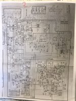
Ok, things went south. For us to help we need to get the big picture. Can you annotate the schematic with as many of these voltages as you can. When something like this happens to me, I find that I did the dumbshit move of plugging the opamp in backward or something equally as embarrassing!
Ok, will do. Oh, I’ve done plenty of stupid **** myself ie reading those resistors incorrectly in the 2 manuals lol. I wish it was something simple as putting the op amp in backwards, even if it would’ve gone bad. I bought 5 just in case but that is 100% correct. I will try to take a picture, hopefully it’ll be clear and I’ll write the voltage at points I checked. I believe that’s what you’re looking for?
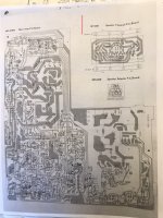
I have a couple pics of the amp portion with some of the voltage and where I checked them. I hope these are what your looking for. Please advise if not and thank you. Joe
Attachments
- Home
- Amplifiers
- Solid State
- Carver MXR-130 Bias help!