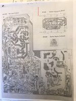
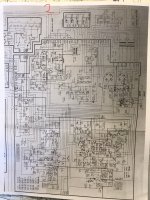
@Potentiallyincorrect @genrose I have a couple pics of the amp portion with some of the voltage and where I checked them. I hope these are what your looking for. Please advise if not and thank you. Joe
Attachments
Sorry about the slow response. It's very hard to read what's what and make sense of things from that markup. Let's pull the opamp and inspect for solder shorts. Leave the opamp out and measure voltages. We need to find a format to communicate them that works better. Send the part number of the opamp you ordered. Need to verify pin out is correct.
Thank you for getting back to me. I didn’t know if you guys get alerts on the thread, that was why I tagged you. I snapped a picture of the op amps labeled new and old. We’re heading to my sons, I’ll grab them voltages most likely tomorrow evening.
is there any relevance that my +/-40v rails dropped to approx+/-26volts?
is there any relevance that my +/-40v rails dropped to approx+/-26volts?
Attachments
In short yes. Too much current is being drawn from the +/- 16 v supplies, or the supplies are bad. Likely the first, now possibly both.
Just dawned on me that the problem might be where I can see! It looks like the +/- supplies get routed to another board (PA509) via connection pins M331 and M332.
Can you provide the circuit schematic for the PA509 board?
My bad for not noticing this earlier.
Can you provide the circuit schematic for the PA509 board?
My bad for not noticing this earlier.
I found the schematic and downloaded it. It looks like the +/-16 V supplies get routed to 3 boards besides the origin board on the main board.
Power flow is as follows. Origin main board > PA509 > (TON509 and FEQ508).
We need to isolate which board(S) are drawing too much power. I would proceed as follows:
1) Disconnect wires at E147 and E148 on board FEQ508, see if +/- 16 V supplies recover. If so, there is a problem in this board, IF not go step 2.
2) Disconnect wires at G152 and G155 on board TON509, see if +/- 16 V supplies recover. If so, there is a problem in this board, IF not go step 3.
3) Disconnect wires at B131 and B132 on board PA509, see if +/- 16 V supplies recover. If so, there is a problem in this board, IF not go step 4.
4) Problem is on main board. (Where we started.)
Do not reconnect any wires / connectors until. we determine which board is at fault. Be careful to not let any of the loose wires too short to anything. Put tape on the ends if possible. If the wires connect via plug in connectors, just unplug entire connector involved. No need to only disconnect wires identified.
Let me know if you understand instructions completely before moving ahead with this debug.
Good luck.
@Potentiallyincorrect, yes sir, totally understood. Hope to be able to get to this a bit later when I ge5 h9me from work. I noticed that supply went to a second board and was going to mention that when we talked again. Looks like your expertise has picked up on a 3rd. I hope to back on later this evening. I am usually a weekend warrior on this stuff because with my job, I never know what time I’ll get home. Thank you again for digging in with me. Joe
@Potentiallyincorrect, I got home a little late last night and started looking through the receiver for the wires you mention to start removing and doing the voltage checks. its going a bit slow. I found a plug that actually runs from the PA509 board and powers the FEQ508 board. That’s where I left off. I hope to hit it again tonight. But I do have a question, if I understand the circuit correctly, and I’m a learner, my psu initiates two different rail voltages. One is +/-60 volts and the other is +/-40volts. Then that voltage is dropped again through the resistors and zener diodes down to the +/-16 volts Which feeds the boards mentioned to test. Is your thoughts there is something on the +/-16vdc side pulling down the +/-40vdc rails?
Will need to work that out after we find the excessive current. More than likely the 40 volt supplies are just drooping because of the excessive current. I suspect that once we isolate the problematic board, the voltages will pop up to levels close to normal. Right now I wouldn't quibble about a volt or less descrepencies. BTW, make sure to observe antistatc precautions when working inside the amp.
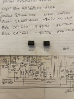
@Potentiallyincorrect, I did things *** backwards but I do have some info. Getting to some of the other boards will require a bit more disassembly. I’ll dig into that this weekend. I found a pair of wires on the MA-508 board labeled M31 & M32 which feeds PA-508 and then the other boards. They were easy to unsolder, so I did. Before I unsoldered them, I checked my voltages to ground. The op-amp is still removed from the socket. i was reading +4.8vdc and -2.1vdc. I unsoldered them and I read the voltage again. This time I’m reading +15.7vdc and -15.4vdc. the Voltages at the zeners came up as well. Just mentioning the 40v rails are still sown in the 26vdc range and i think I should mention my 60v rails are +/-40vdc. Also, it may be nothing or possibly relevant, I’ve noticed and perhaps should’ve mentioned it in previous conversations but my display for the tuner does not work anymore. I know it’s one step at a time, I’m just trying to give as much information as possible.
Moving on, I soldered M31 & M32 back in and checked the voltages on them and once again, the +/-16vdc was back down to +4.7vdc & -1.9vdc. I found a plug on PA509 which feeds board FEQ508. I unplugged it and the voltages came up to roughly -12 and +13vdc. I will do the check out procedure as you suggested and report back as later this week unless directed differently.
Moving on, I soldered M31 & M32 back in and checked the voltages on them and once again, the +/-16vdc was back down to +4.7vdc & -1.9vdc. I found a plug on PA509 which feeds board FEQ508. I unplugged it and the voltages came up to roughly -12 and +13vdc. I will do the check out procedure as you suggested and report back as later this week unless directed differently.
Now the 60 v supply’s are at 40 ????? That creates a bunch of new questions. Hold off till I can think about that.
Ok, we need a bit of a sidetrack before continuing with the original problem.
If you have been using some kind of a voltage limiter like a dim bulb or a variac, please let me know before proceeding in with the next debug steps, as that will likely change the plan of attack.
Next measurements, use ACV setting on your multimeter. Many of these nodes may be at full line voltage!
(Use great caution, if not sure of yourself stop and read the thread on HV safety practices). Or just stop!
Also, when making any measurement, make sure there is clear access and stable contact with the measurement nodes. A slipped probe can make a real mess of things as well as being a safety hazard. I have soldered a short stub of wire to clip to help avoid such issues when access is difficult or requires too many hands (hands greater than 1!). I apologize if all this is already obvious for you.
1) Measure secondary voltages of the main transformer. Specifically, nodes labeled on the main board as M124, M125, M126, and M127 all with respect to M123.
2) Measure primary voltages on transformer (Again HV AC safety warning). Specifically, nodes on the main board labeled as M113, M115, M116, M117, and M119 with respect to M114.
@Potentiallyincorrect, I got stuck late again at work and going to shower, eat and pass out. I do commercial/industrial HVAC and the first warmer days in Chicago freaks everyone out. I’ll get those voltages tomorrow night. I actually checked all of those points a couple days ago and I don’t remember what they were offhand. They didn’t seem right in my mind. And yes, electrical safety is priority. I deal with very high voltages with my job as well. I will get that info tomorrow evening.
I got stuck late again at work and going to shower, eat and pass out. I do commercial/industrial HVAC and the first warmer days in Chicago freaks everyone out.
When the receiver arrived, initially I visually inspected it and after it looked ok, I did use a dim bulb. When it seemed ok after a very short period, I went to the line. I had 61vdc on the cathode of the diode checking alignment and I also had the 40vdc. I’ll get those voltages tomorrow night. I actually checked all of those points a couple days ago and I don’t remember what they were offhand. They didn’t seem right in my mind. And yes, electrical safety is priority. I appreciate all of the advice. I deal with very high voltages with my job as well. Thanks again.
When the receiver arrived, initially I visually inspected it and after it looked ok, I did use a dim bulb. When it seemed ok after a very short period, I went to the line. I had 61vdc on the cathode of the diode checking alignment and I also had the 40vdc. I’ll get those voltages tomorrow night. I actually checked all of those points a couple days ago and I don’t remember what they were offhand. They didn’t seem right in my mind. And yes, electrical safety is priority. I appreciate all of the advice. I deal with very high voltages with my job as well. Thanks again.
Last edited:
Yea, I get that, my neighbor just decided to put in a new HVAC. Get your rest, we can continue when you are ready.
@Potentiallyincorrect, I took the voltages requested from last nights thread.
With reference to M114
M113= 123.4 vac
M115= 27.9 vac
M116= 27.9 vac
M117= .031 vac
M119= .031 vac
With reference to M123
M124= 9.32 vac
M125= 9.31 vac
M126= 9.32 vac
M127= 9.30 vac
With reference to M114
M113= 123.4 vac
M115= 27.9 vac
M116= 27.9 vac
M117= .031 vac
M119= .031 vac
With reference to M123
M124= 9.32 vac
M125= 9.31 vac
M126= 9.32 vac
M127= 9.30 vac
This is getting complicated. It looks like full power is not reaching the power transformer. M115 and M116 should be close to full line voltage, so something in the power control circuitry is messed up. I also think there is likely a measurement error in your secondary voltages.
Given the primary is only getting 28 volts, the voltage on M124, and M125 look about right (9.3 V). The voltages on M126 and 127 do not make sense. Again, given the primary voltage, I would expect M126 and 127 to measure about 14 volts. It makes sense to remeasure these voltages and make sure you are probing the correct nodes.
So how to proceed? There is an off chance the power switch PWS-508 has bad or dirty contacts. Try using a contact cleaner on the switch. Spray into all the switches crevices and operate several times (with the unit unpowered) and let dry. Then retest the voltages, this might take several attempts.
Let's see where that gets you as next debug steps can be considerably more challenging.
Hi Joe,
One issue at a time.
Finger test on the op amps is a valid test. If they don't get warm enough (would love a thermal camera), then desolder pins 4 and 8 on each to see if your supplies come back up. Then connect one op amp at aa time to see when the supplies go down. Now be careful, if you substitute an op amp, you may need to recompensate the amplifier. Some op amps simply don't play nice in some circuits. This means you absolutely do require an oscilloscope and THD meter if you decide to "upgrade" op amps. If you don't have a 'scope, you really are working blind, but should never, ever "upgrade" an op amp. Oscillation is generally supersonic (you can't hear it) and may serve to heat up the output stage or cause other issues.
Now, an FL display needs a few things to work. First check for heater voltage, normally the end pins and should be 2.5 to 3.5 V depending on the unit. I haven't looked at this display yet. Also, you need approximately -25 to -30 VDC bias on the heaters. Also check the 5 VDC supply for the processor.
One comment I'd like to make, and it drives me nuts. Often someone will comment "I got it cheap to learn on, so it doesn't matter". Well, it does. You aren't going to learn anything if you aren't careful and do things while asking advice. That's cool. So if someone is just going to hack away at something, please give the unit to someone who will make an honest effort to repair it properly. I hate seeing equipment destroyed due to an ego - or whatever. Also, there may come a point where you simply do need more experience and / or equipment than you have. You know, a good technician is actually a skilled professional who has vast knowledge on parts and circuits. You can learn a lot from them, but never assume that service is simple. There is a lot to consider and just because something works, it doesn't mean it is properly repaired or operating to spec.
I don't mind helping someone who will make an honest attempt to repair something right. For yourself, that's fine. If you're charging for it, or it is for a friend, you owe it to them to have the job not only done right, but confirmed to be working properly. There are zero excuses, but it is easy to give yourself a pass. I am trying to be helpful here.
-Chris
Oh boy! It isn't the power switch for sure.
STOP!
The AC voltage is regulated before reaching the mag coil (a type of transformer). These transformers NEVER receive full AC power - ever. The protection circuit and voltage sensing will regulate the power, so you have a problem in those areas. Locate and correct that first.
You are actually at a point where you can cause destruction of the entire unit. Trained Carver techs do know how to power these up carefully not using the power regulator circuit, but it has to be done carefully and is only used for troubleshooting.
Please go back over what you have done, double check all your work and any replaced components. Look for solder shorts between traces as well.
-Chris
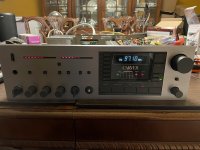
Hello guys, happy Saturday and so far it’s been a good day. @Potentiallyincorrect and @anatech, I’m sorry for dragging you guys down a path of my own silliness. Anatech, I took your advice and backtracked my steps because rethinking the process working with potentially incorrect and he rose earlier, i had good rail voltages and wasn’t having the display issue. In my travels of unsoldering R655 & R657 checking for +/-16vdc, there was a slight overflow of solder touching another terminal😱. That was a stupid mistake that could’ve been catastrophic. I cleaned that up and all my voltage’s on the higher rails jumped right up to +/-61vdc and +/-40vdc, the display came back to life and the unit is functional. I installed the original op amp and bias points again, which is where this whole thing started and I still get no bias voltage across the test points. I tried the new op amp in its place which is the same op amp, only new which made no difference. I still can’t bias the amp. Can we move back to troubleshooting my original
@anatech, I’m playing around with this little project for my own enjoyment. I have no intentions selling my work as a repair, rigging anything or making something work just enough but not to spec. This is why I came to the DIY forum for help. I built some of the First Watt/Nelson Pass projects with great success. The forum was great when I needed help because I am a newbie. I mentioned I got this receiver super cheap on eBay and it would be a learning process if I blow it up. I would learn not to try to repair Carver equipment and stick to building. I do have a scope, signal generator but not a distortion meter.
With that being said, can I ask you guys to continue to assist so I can hopefully conquer my bias issue on this MXR130? Thank you both in advance.
Attachments
- Home
- Amplifiers
- Solid State
- Carver MXR-130 Bias help!