Just pulling your leg George 🙂 . OK I will admit the DL109 Hans shows was an impulse buy but all the others in that shot were well reasoned (and used and cheap).
Thx - it had to be something like that. I rechecked too and think all's well. LDI found the 6dB shift, I was finding the peak harmonic bin but taking the value of 2 bins over which amounts to a ~6dB shift down, it was a factor of 2 after all. The difference now is just noise.
I know but I’ll keep watching you.😀Just pulling your leg George 🙂
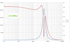
Just as a first test to check everything, here the inductance of the AT150MLX with 4.5mV applied.
Great.
Impressive results Hans.
Can you share info on the test setup, equipment and methodology?
George
I know but I’ll keep watching you.😀
George
Wouldn't expect anything less!
George,I know but I’ll keep watching you.😀
Great.
Impressive results Hans.
Can you share info on the test setup, equipment and methodology?
George
I'm almost there, but still working on fine tuning and noise suppression with low level signals.
When I'm satisfied with the results, I'll let you know what I did.
But it's Eastern, and my family needs my attention.
Hans
Attachments
Do you mean loading for playing with a virtual gnd input ?How to load this cartridge: inductance = 30mH, DCR= 91 ohms.
In that case use the excel spreadsheet below after having renamed it back to Aurak.xlsx
Hans
P.S. Depending on the Excel version that you have, either use a decimal comma or a point.
Attachments
Last edited:
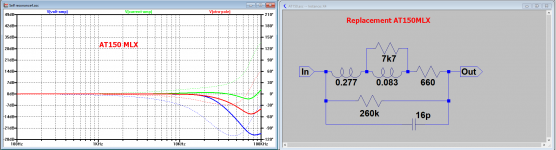
I'm still working on the measurement set up, but results for the AT150MLX are good enough to be translated into a replacement circuit and that's what I wanted to show already for eventual comments.
The first image below shows the replacement circuit, its FR through a 47k //150pF amp in blue and through a virt. gnd amp in green.
The latter also with an added 6usec filter in red.
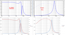
The second image shows the measured data versus the simulated results.
Measured and simmed go from 360mH to 325mH, have peaks at 370mH, an Fres at 56kHz, where the modulus is 215K and a par. cap of 16pF.
The only small difference is that in the measured data the inductance rolls off slightly earlier, but for the rest everything is the same.
A bit surprisingly, the value of the part of the coil with the par. resistor comes quite precise, in this case 0.083mH.
Hans
The first image below shows the replacement circuit, its FR through a 47k //150pF amp in blue and through a virt. gnd amp in green.
The latter also with an added 6usec filter in red.
The second image shows the measured data versus the simulated results.
Measured and simmed go from 360mH to 325mH, have peaks at 370mH, an Fres at 56kHz, where the modulus is 215K and a par. cap of 16pF.
The only small difference is that in the measured data the inductance rolls off slightly earlier, but for the rest everything is the same.
A bit surprisingly, the value of the part of the coil with the par. resistor comes quite precise, in this case 0.083mH.
Hans
Attachments
It's been a long weekend so I may have missed something, but does it need as low an additional filter as you have added there? In current mode it looks pretty flat up to CD4 frequencies.
Really interesting measurement. Thank you again for sharing.
Really interesting measurement. Thank you again for sharing.

Thx - do you have sketch schematic of the test set up, and what is the test stimulus level pls?The second image shows the measured data versus the simulated results.
LD
I suppose about now might be a good time to return to the matter of the real part of coil impedance which we can see becomes significant near resonance in a relatively low Q way? As it's real, energy loss must go somewhere, and it must be a Johnson noise source. Is this true, and if so how does that happen given all we have is a bit of bent wire ? 😉
LD
LD
. Is this true, and if so how does that happen given all we have is a bit of bent wire ? 😉
LD
Heat, the model fits losses to resistances some are easy to understand like series resistance but any loss like eddy current and skin effects will usually end up as heat at these frequencies I don't think much is radiated away.
I must have digested something malign during eastern brunch.
I’m sick as a dog, hopefully tomorrow I can make a big leap with the remaining Carts.
In the meantime I found why there was a small discrepancy between measured and simmed results where the measured inducance started somewhat earlier to roll off.
My test gear, showing the details later, has a 14pF//1 Meg input.
I included the cap in my sim, but forgot the 1Meg. This results in a small correction of the replacement circuit that I will also show tomorrow.
Now back to bed again.
Hans
Hope you soon feel better Hans.
But although loss mechanisms such as eddy currents are proportional to repetition rate, ie frequency, that is aside to the main loss mechanism due to induction ie rate of change of flux.
I don't see how resonance increases real loss. 'In the moment' the system can't know whether it's resonant or not...………………?
Is not this phase change an artefact of the resonant system, and therefore lacks real properties of resistance such as energy loss to heat and Johnson noise? If so, how is that? Does the spectrum of Johnson noise follow the Re versus f curve?
LD
The problem, as I see it, is that this real impedance is associated with the resonant system and follows the well known laws of resonant systems as a function of frequency.Heat, the model fits losses to resistances some are easy to understand like series resistance but any loss like eddy current and skin effects will usually end up as heat at these frequencies I don't think much is radiated away.
But although loss mechanisms such as eddy currents are proportional to repetition rate, ie frequency, that is aside to the main loss mechanism due to induction ie rate of change of flux.
I don't see how resonance increases real loss. 'In the moment' the system can't know whether it's resonant or not...………………?
Is not this phase change an artefact of the resonant system, and therefore lacks real properties of resistance such as energy loss to heat and Johnson noise? If so, how is that? Does the spectrum of Johnson noise follow the Re versus f curve?
LD
Last edited:
Put another way, if the noise is not white where does the extra energy come from?Does the spectrum of Johnson noise follow the Re versus f curve?
LD
Last edited:
- Status
- Not open for further replies.
- Home
- Source & Line
- Analogue Source
- Cartridge dynamic behaviour