And what was your conclusion, like Pinkmouse nothing or a nirvana?aHobbit said:But I tested it ...
Peranders,why don´t you just try it for yourself instead of just debating this and even starting a thread about at the swedish hififorum.peranders said:
And what was your conclusion, like Pinkmouse nothing or a nirvana?
I guess that if you dont hear any differences between AD8610 and OPA627 like you said at www.hififorum.nu you will not be hearing any differences with or without the "snubber"....
I have not tried this myself but I will probably do that some day.
Upupa Epops said:To Nicke : Maybe all is different - somebody brave must shout out " King is naked ! " 😀 .
And maybe someone has to try before shouting it out 😉
Ok, I'll change my statement a bit: I can't hear any difference if I can't have two identical set ups and change fast between those two.
When I have had opportunity to change fast like in my QRV-04 and QRV-07, even then I have had a hard time to pick the difference and in those cases I really wanted that.
Zero ohm vs 10 vs 100 ohms out to a 150 ohms headphone => not detectable change altough measurements shows a 0.25 dB bass lift.
Running the BUF634 at max speed and medium speed. Zilch i difference altough the distortion will be a bit lower with more current.
My point is that many of us claim more than they are willing to bet money on. Sometimes we have a rather unhumble attiude towards our impressions and others too.
I asked before have many skilled designers (only Peter Danile answered...) which use "snubbers" (not the right word I know) and I'll suspect NONE does. If I'm wrong I would gladly be corrected. I don't deny that this tuning of the power might be a good thing, to really take care of everything. I will test it later on but for now I leave it as an idea, good one and Carlos should be proud of himself.
I think it's good if we can have a mature debate instead of a tug of war. Things aren't black or white. We will always have believers which don't need so much in order to believe and we have those who don't believe no matter what and many inbetween.
Some people has a low level before they try, no harm in that but I'm not like that.Nicke said:And maybe someone has to try before shouting it out 😉
It is worth noticing that most "triers" also confirm positive results. Pinkmouse was an exception here.
Hands up: Have many that have peeled cap jackets off experinced good results? Have many do it anyway?
Have many which have made their own mains filter have got positive results?
Have many modders have really been honest to themselves?
PS: Nicke, om du skriver vad du sysslar med på engelska så förstår andra än svenskar ditt budskap, Ok Mr. D förstår nog också. 🙂
Not for sure until something is prooved. All those people may have very sharp ears so don't rule out this but I'm in total agreement with Mr. Didden here.... but my guess is that there are many sugarpills out there....
Nicke said:
Peranders,why don´t you just try it for yourself instead of just debating this and even starting a thread about at the swedish hififorum.
I guess that if you dont hear any differences between AD8610 and OPA627 like you said at www.hififorum.nu you will not be hearing any differences with or without the "snubber"....
I have not tried this myself but I will probably do that some day.
Nicke, pretty many have read it but a very few has anything to say, not even you. You don't move a debate forward just by saying "why don't you test it yourself".
You can't exchange ideas and opinions via telepathy.
Hi all! I would like to jump in just for a moment, there is work waiting..
Dear Thorsten!
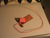
I would like to ring an alarm here - depending on the realization, but you can have problems with such a setup. Reading your words, and keeping in mind my results with 100nF bypassing, and the resulting ringing related to the wiring inductance, I had a slight suspect. You, rightfully, went up with the capacitance value suggested, but is it enough? And then, you know, who has a hammer, is looking for nails..
So I made a dummy realization of your bypass setup, with a possible wiring config, what I would imagine like practical.
Here it is:
Once you do that sort of thing simply placing a nice low inductance 4.7uF Epcos stacked film cap across the Chip's +V & -V pin and a second from -V to nominal ground and using high capacitance cables to carry your battery current and all our problems simply go away....
Dear Thorsten!
I would like to ring an alarm here - depending on the realization, but you can have problems with such a setup. Reading your words, and keeping in mind my results with 100nF bypassing, and the resulting ringing related to the wiring inductance, I had a slight suspect. You, rightfully, went up with the capacitance value suggested, but is it enough? And then, you know, who has a hammer, is looking for nails..
So I made a dummy realization of your bypass setup, with a possible wiring config, what I would imagine like practical.
Here it is:
Attachments
Upupa Epops said:To P - A : Yes, " placebo effect " 😉 .
Those subject to the medicinal placebo effect actually get well.
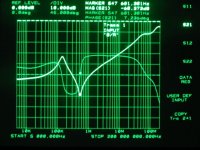
I did not have those nice Epcos thingies what you were talking about, but I suppose that there impedance curve would be quite similar to the
Wima, with ESL a bit less, but not enourmously less!
What are the important factors here are the capacitance, ESR and the stray wiring impedance, over which, when suggesting such a setup, you don't have control, different people will use different cable lenght, somehow they will have to connect that physically big piece of battery!
And, as it is visible, that Wima has the lowest ESR up to now shown!
And I think, this is the exact problem.
Then, one might say, all this still might sound well, but having ~180 degree phase shift at 500 kHz on the power pin of this chip? I would smell trouble...
Please, again, do not take this as an attack, really, I understand Your idea of using quality parts, and I have to tell that I appreciate very much your approach in general. I just thought of jumping in here, because I could control the result of your setup.
Konnichiwa,
Yes, hence I was VERY SPECIFC to the whole thing, including the require for a low inductance supply cable.
Funny, I do not see the low inductance wiring specified (eg copper foils or heavy coaxial cable) and no Battery. So no, it is NOT what I specified....
As expected, if you do not follow specifications.... ;-)
The ESL is enormously less actually. Try them.
Actually, my original suggestion VERY EXPLICITLY did require such a control. Here is what I wrote:
Now it is not my fault if people cannot read.... ;-) But I explicitly specified high capacitance wiring, in other words, minimal stray inductance wiring.
Please take an Epcos Cap and a piece of RG223 Cable and bridge at the end using a workable model of an SLA combo of 2 X 12V/12AH in series. That will look rather different I should think.
Sayonara
Joseph K said:I would like to ring an alarm here - depending on the realization, but you can have problems with such a setup.
Yes, hence I was VERY SPECIFC to the whole thing, including the require for a low inductance supply cable.
Joseph K said:So I made a dummy realization of your bypass setup, with a possible wiring config, what I would imagine like practical.
Funny, I do not see the low inductance wiring specified (eg copper foils or heavy coaxial cable) and no Battery. So no, it is NOT what I specified....
Joseph K said:And the response of this setup:
As expected, if you do not follow specifications.... ;-)
Joseph K said:I did not have those nice Epcos thingies what you were talking about, but I suppose that there impedance curve would be quite similar to the Wima, with ESL a bit less, but not enourmously less!
The ESL is enormously less actually. Try them.
Joseph K said:What are the important factors here are the capacitance, ESR and the stray wiring impedance, over which, when suggesting such a setup, you don't have control,
Actually, my original suggestion VERY EXPLICITLY did require such a control. Here is what I wrote:
Kuei Yang Wang said:I suggest to use Sealed Lead Acid batteries for DIY Soild State Gear.
<snip>
Once you do that sort of thing simply placing a nice low inductance 4.7uF Epcos stacked film cap across the Chip's +V & -V pin and a second from -V to nominal ground and using high capacitance cables to carry your battery current and all our problems simply go away....
Not practical for a commercial Amp, but this here is DIY Audio, ain't it?
Now it is not my fault if people cannot read.... ;-) But I explicitly specified high capacitance wiring, in other words, minimal stray inductance wiring.
Please take an Epcos Cap and a piece of RG223 Cable and bridge at the end using a workable model of an SLA combo of 2 X 12V/12AH in series. That will look rather different I should think.
Sayonara
How much in numbers, 10%, 20% 50%, 3000%?Kuei Yang Wang said:The ESL is enormously less actually.
Thorsten do you have a type number for the part you are refering to?
Konnichiwa,
The Epcos 4.7uF has it's resonance at appx 2MHz, meaning the ESL would be around 1nH vs the around 20nH for the measured result of the Wima part. ESR should be < 20mOhm.
Not off hand. These are just generic "silver" uncoated stacked film types. Nothing fancy or excotic
Sayonara
peranders said:How much in numbers, 10%, 20% 50%, 3000%?
The Epcos 4.7uF has it's resonance at appx 2MHz, meaning the ESL would be around 1nH vs the around 20nH for the measured result of the Wima part. ESR should be < 20mOhm.
peranders said:Thorsten do you have a type number for the part you are refering to?
Not off hand. These are just generic "silver" uncoated stacked film types. Nothing fancy or excotic
Sayonara
Metallized Polypropylene (MKP/MFP), 4.7 uF has resonance at approx 500 kHz according to datasheet. No value for the round type, probably much lower.Kuei Yang Wang said:The Epcos 4.7uF has it's resonance at appx 2MHz, meaning the ESL would be around 1nH vs the around 20nH for the measured result of the Wima part. ESR should be < 20mOhm.
Metallized Polyester (MKT) stacked has 90 kHz.
2 MHz sounds pretty fantastic to me. Are you sure about that?
The b3256x (stacked) SilverCap seemt to have a fc of slightly above 1 MHz for the 4.7u.
The evox rifa mmk (finns på elfa) 5mm leg spacing seems to be around that performance as well the 1u fc is at 2MHz.
The evox rifa mmk (finns på elfa) 5mm leg spacing seems to be around that performance as well the 1u fc is at 2MHz.
Thorsten
The part numbers for the Epcos PETs described seem to have the following prefixes, B32560 and B32564. They are described as radial lead uncoated caps in the range of 1pF to 33uF. Are these the ones you suggested or do you prefer the MKP/MFP parts? I would also like to refer you to my earlier post asking at what value will the ESL begins to degrade the sound using a 24V or 12V battery supply? Will anything larger than 1nH sound less good or just look less good?
🙂
- Status
- Not open for further replies.
- Home
- Amplifiers
- Chip Amps
- Carlos' snubberized Gainclone Power supply