Sorry, but what pulse are you talking about? Risetime, length, current etc?
I'm sorry but I can't see any real situation when you are driving the amp in to heavy clipping and even so how does the wave shape of the PS current look like?
I'm sorry but I can't see any real situation when you are driving the amp in to heavy clipping and even so how does the wave shape of the PS current look like?
Let's just get some numbers and calculate.
http://www.maxim-ic.com/appnotes.cfm/appnote_number/907
or
http://www.hagtech.com/pdf/snubber.pdf (Page 6)
P=CfV^2
For 2V @ 200kHz on the rail (hope it's conservative enough) and 100nF cap I calculated 80mW dissipation in the resistor. That's if you see continues 2V/200kHz signal on the rails. So I think 1/4W res is plenty.
/Greg
PA
Add some inductance to your sim to represent the secondary impedance of the transformer -- for a couple of the torroids I have used it can range from 15 to 100 uH, (for the LM3875 amp I have on my desk it's 62uH, for the LM4780 bridged amp its only 15uH). Use the pulse generator to switch the gate of an ideal HexFET which switches the load from 3 amps to 100 milliamps -- it's the quickness of the change in load which determines the ringing that the snubber is thwarting.
the thermal protection of the Overture series kicks in very quickly -- there's no slewing -- (there is a latency period where it seems to be making up its mind whether to kick in!) so in some sense you have to contend with the issues a switching power supply designer deals with --
Hi,
now lets get some other numbers and calculate. At 200kHz capacitive impedance of 10000uF rail cap is only 7.96E-5 Ohm, so it can be neglected. If I assume a very conservative ESR of 50mOhm, 40A at 200kHz is required for 2Vripple. That would produce 80W of losses in bulk rail capacitor. So I think arguing about losses in snubber resistor is a little off topic.
Best regards,
Jaka Racman
No, and the thread isn't about that.jackinnj said:ever measure the secondary inductance AND the interwinding capacitance?
I'm bringing this thread alive again.
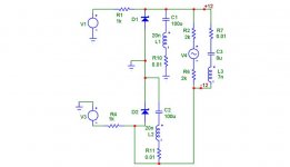
I'm claiming that this snubberization isn't done all the way.
Purpose: Bringing down resonance peak which the LM3886 sees, not far away. There the important thing to remove resonances' at the supply pins as the most important task, the second importrant is to remove the resoance further away.
Anybody who agrees with me?
Check carefully the pictures below. The original picture can be found in the first post.
Below we have a locally snubberized decoupling.
Attachments
PerAnders, I've seen many of your posts and your site. You are much better at this stuff and I will ever be.... but I have a comment on the .1uF cap you seem to dislike.
I thought the purpose of the .1 uF capacitor was to dampen high frequency oscillations due to the diode bridge, not to impart beneficial impedance characteristics. So the fact that the impedance looks bad might be true but in when the diodes start ringing, you might have an overall better system with the .1 caps in place.
I thought it was relatively common for one to use a bypass cap after the bridge, say .1 or .47 or .01 uF
anyway, just my thought, sorry to intrude.
It does matter _where_, physically this unsnubbed 100 nF is located. If it's close to the snubbed capacitor it's pretty useless to have the snubber at all.
lgreen said:PerAnders, I've seen many of your posts and your site. You are much better at this stuff and I will ever be.... but I have a comment on the .1uF cap you seem to dislike.
I thought the purpose of the .1 uF capacitor was to dampen high frequency oscillations due to the diode bridge, not to impart beneficial impedance characteristics. So the fact that the impedance looks bad might be true but in when the diodes start ringing, you might have an overall better system with the .1 caps in place.
I thought it was relatively common for one to use a bypass cap after the bridge, say .1 or .47 or .01 uF
anyway, just my thought, sorry to intrude.
The diode snubbers -- (actually they are to compensate for the LC tank formed by the transformer secondary inductance, transformer secondary to primary capacitance and diode capacitance) -- should be placed as close as possible to the diodes -- note that these snubbers should be RC -- you can get the formula from Hagerman's website -- typically the capacitance in a diode snubber will be 1nF to 10nF.
the supply bypass capacitor to the filter capacitor (100nF) should be placed as close to the filter cap as possible. it really isn't a "snubber" as the term is defined in smps power supply books. of course, that's why engineers aren't lawyers and vice versa.
having the snubber cap removed from proximity with the filter cap makes them about as useful as teats on a bull.
Hello all, where are we now with this design? Any other problem found? Is it ready to use in replacement of carlosfm design?
I ask this because I'd like to change the alim of my GC. I' m not realy good at theory so I ask before wasting components 🙂
I'm using stereo configuration (one 320VA 2*22v toroïdal) how should I modifie your design to use a single toroïdal?
Sorry for noob questions, I was interested by this design because it seem to improve the quality of the sound. I generaly follow design from other and when I've built it I understand why it is like that.
Best regards gogou
You can do in three ways:
1 As everybody else including high-end manufactures
2 My way and also Matti Ottala (finnish famous amp designer in 70's) and surely a lot more people.
3 Carlos way.
Test all three and come back if you can pick any significant difference.
1 As everybody else including high-end manufactures
2 My way and also Matti Ottala (finnish famous amp designer in 70's) and surely a lot more people.
3 Carlos way.
Test all three and come back if you can pick any significant difference.
Hi Peranders,
I understand your idea to insert in series to the lowcap a resistor to absorb the peak of resonance, and your sizing is good.
I want however explain any things:
all the " real cap " have a peak of resonance.
You have to decide your priority. Serve you a very lower impedance? You have to use a "fall" of 1/2 value of cap (without snubber, ie 1uF+0.5uF+0.25uF) completely the range of frequencies that you maids.
You wants have a good linearity of impedance (but "high") ?
You lead in series to the cap a resistor.
If you increase the impedance of a PSU it is always more linear, but lead effective, kind for the noise.
A lowcap + res of 2 ohms, as you,has an effectiveness of noise filters (and line impedance) too low of 20-30dB (min).
I want explain that snubber serves to absorb the peaks in SMTP circuits, and not for linearizing the impedance.
Then "snubber" isn't good definition, for this application, but this is not important...
If the linearity of impedance is important in audio, the problem not it may be the lowcap from 100nf, because it works at over the 3Mhz...
I believe that the linearity of the PSU impedance is important, but here doesn't see circuits studied to be linear in audio band, but in RF band (10Mhz+).
Ciao
Mauro
I'm not 100% sure what you mean but in some points your are right.
1 Snubbers _must_ be used in certain switching applications otherwise you'll kill the transistors, thyristors etc.
2 Snubber is the wrong word here, I know, but we have agreed sort of to use "snubber" as impedance equalizer.
1 Snubbers _must_ be used in certain switching applications otherwise you'll kill the transistors, thyristors etc.
2 Snubber is the wrong word here, I know, but we have agreed sort of to use "snubber" as impedance equalizer.
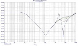
This is a simulation for various value of " R snubber".
The main impedance down curve (100Khz low peak) it is caused to 100uF caps, and for my opinions it's the only element of tecnical discussion...
the peak at 2 Mhz it's the "normal" 100nF resonance value, following of a bot peak at 8 Mhz...
The intermediate curve: brown =0.5ohm, geeen 1ohm, etc...
The most "linear" curve, dark blue = 2ohm.
The problem: The RC value absorb (-13dB) the "bad" high impedance value at 2Mhz, but all the "good low impedance" at 3 to 20Mhz it is very increase...
Attachments
- Status
- Not open for further replies.
- Home
- Amplifiers
- Chip Amps
- Carlos' snubberized Gainclone Power supply, Part II