To Simont : It is nonsens - give there small resistor, touch him by finger and make clipping - resistor stay cold.
Upupa Epops said:We are talking about " snubber " resistor, isn't thruth ? How is it related to amp's clipping ? Or do you mean, that by clipping amp work like recuperation diode ?
when the amplifier clips, or goes into a mode in which the thermal protection is cycling on and off quickly, the output harmonic spectrum far exceeds the audio spectrum -- so the 100nF or 330nF starts to do its job. you could view it by measuring the voltage drop across the 1R resistor.
the thermal protection can cycle very quickly between 165 and 155 die temperature -- if you have a big heat sink -- this is for conditions which violate the SOA conditions for the chip -- you can see it on a scope. when the thermal protection kicks in the current drawn by the chip also changes -- it oscillates!
my belief is this --- there is a need for the 100nF decoupling snubber on the V+/V-, as well as on the output of the amplifier. I don't think the minimalist approach works if you are pushing the ampchip to its max.
the situation is probably worse still for the LM3886TF with its insulated case -- the TF can not be pushed as hard as the non-insulated versions. the thermal resistance of the insulation is simply too high. I don't think that there is any reason to use the TF in a DIY amp, but I can think of reasons why JBL or someone would use it in a consumer product.
i guess I prepare for the "worst-case" scenario --
Upupa Epops said:To Simont : It is nonsens - give there small resistor, touch him by finger and make clipping - resistor stay cold.
you aren't trying hard enough: here's a snap of the bottom side of my "dummyload" -- 5 40 ohm, 40 watt precision power resistors in parallel -- and you can fry an egg on it ! -- or melt the scotch tape dispenser as was inadvertently done here.
An externally hosted image should be here but it was not working when we last tested it.
fwiw, I use a 1 watt resistor on the output snubber (I prefer to call it a zobel).
the diode snubbers I use -- really depends on the transformer you rae using.
I will say that I seem to hear improvements at all listening levels, not just when it's loud. In fact I've not taken it very loud at all yet... just on the verge of p;ss;ng other people in the house off, so 'moderate'. Only medium term listening will tell if what I hear is in my mind or not, I don't think it is at this point, the improvement is simply too great.jackinnj said:my belief is this --- there is a need for the 100nF decoupling snubber on the V+/V-, as well as on the output of the amplifier. I don't think the minimalist approach works if you are pushing the ampchip to its max.
Was an ordinary heater not enough for this room?jackinnj said:5 40 ohm, 40 watt precision power resistors in parallel -- and you can fry an egg on it !

Is 1w sensible for the zobel then, or simply what was to hand?
Is 1w sensible for the smoothing cap snubber?
What values and ratings do you use on your bridge snubbers? Can this snubber be done to good effect without measurement?
Do you use a cap across the transformer secondaries, too?
Thanks!
Upupa Epops said:I'm talking about snubber at PS, not at output ! Jesus !
the one on the power supply is called a decoupling capacitor -- and it will pump a lot of current if the amplifier goes into the extreme conditions I described -- you can demonstrate it by overdriving the amplifier.
the energy stored in the snubber or decoupling capacitor is dissipated by the resistor, whether that resistor is on the power supply decoupling capacitor, or on the output of the amplifier. the energy dissipated by the resistor is:
P = C* f *V
Numbers please. How much is "substantially"?jackinnj said:
if the amplifier clips, there is a lot more power (than a microwatt) being dissipated by the resistor !!!!!
other thing to note -- if there is an overvoltage situation (which will happen with an inductive load like a speaker or motor -- the reverse voltage can substantially exceed the rail voltage -- the inductor acts like the storage inductor in a switching power supply -- National discussed this in an application note in 1993 -- the chip itself is protected from the over-voltage -- the snubber isn't.
If you have 10000 uF and you have inductive energy, how much will the voltage increase?
Jack, please check the schematic in the first post. This is what we discuss and we call the R+C for "snubber" which isn't totally right (I know) but there is a name on it now and most of us know that this is what we refer to.jackinnj said:
the one on the power supply is called a decoupling capacitor -- and it will pump a lot of current if the amplifier goes into the extreme conditions I described -- you can demonstrate it by overdriving the amplifier.
the energy stored in the snubber or decoupling capacitor is dissipated by the resistor, whether that resistor is on the power supply decoupling capacitor, or on the output of the amplifier. the energy dissipated by the resistor is:
P = C* f *V
peranders said:
Jack, please check the schematic in the first post. This is what we discuss and we call the R+C for "snubber" which isn't totally right (I know) but there is a name on it now and most of us know that this is what we refer to.
I did check the first schematic -- they are all 'snubbing" in a manner --
the points I am making are in respect of the 100nF on the power supply AND the 100nF/2R7 output to ground on the ampchip is under conditions of stress.
when the thermal protection kicks in, or when the amp is driven to clipping it can cycle very quickly -- when I stress tested one of my amplifiers on a big heat sink with forced air cooling you could hear the thing squeal when it was pushed beyond the SOA. -- the heat sink was doing its job unmercifully as the die of the chip went into thermal shock, shut down and then recovered.
as I said before, I replaced some "charred" snubber resistors on the output -- they hadn't gone completely wonky but they clearly showed that they were cooking.
I have also observed a latency period for the protection kicking in -- when the chip is making up its mind the distortion kicks up to over 1% pretty steadily -- I wouldn't recommend this as general practice -- it's like burning out a clutch on purpose.
peranders said:... so I'll doubt that you will need several watts in the resistors.
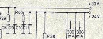
EC-Otala amp
R39,40=1ohm/1W
C8,10=680nF, C9,11=100nF MKT
Attachments
Don't forget that you don't know really why Mr. Otala has chosen the parts that he has done. Just becuase he has 1 W doesn't imply that it's really needed.
I have attached my snubber simulation which maybe has simplifications. You can see for yourself how small the current is through the snubber.
I have attached my snubber simulation which maybe has simplifications. You can see for yourself how small the current is through the snubber.
Attachments
To P-A : It's amazing, how big is inertia in thinking 😎 . Otala use it probably because it was fitted directly on elyts without any PCB and with bigger type is in this case more easy manipulation. That's easy explanation, but only for somebody 😉 .
Keep it goin guys!! I am getting mental kicks out of this, my understanding of electronics is greatly increased by this type of "fights". Keep on explaining to eachother! It seems that the best explainations come from the wish of proving someone wrong. Amp-fights are the best!!!
My first claim is that this rather small peak in the impedance curve is of minor importance.
My second claim is that this alone C2, C7 should be removed.
So anybody who agrees with me? At the moment we are not talking about how the parts should be chosen when it comes to values and ratings.
It looks like this snubber resistor could be rather small in wattage rating.
My second claim is that this alone C2, C7 should be removed.
So anybody who agrees with me? At the moment we are not talking about how the parts should be chosen when it comes to values and ratings.
It looks like this snubber resistor could be rather small in wattage rating.
PA --
I use a 1 milliohm resistor as a current shunt in Multisim8.
Put a pulse signal between the sine source and the capacitors -- this will simulate the boundary conditions in which the amplifier quickly turns on and off -- this is what you will observe on an oscilloscope -- there is an "envelope" of energy -- if the amplifier is going into clipping the pulse is pretty small, but very fast -- try 1 V at 10kHz. -- if the amplifier is at the border of going into thermal protection the pulse is much larger, but much slower.
i agree that in a steady state, when the amplifier isn't driven beyond its SOA, the snubber resistor doesn't see a lot of current, but in the conditions I described -- where the amplifier is shutting itself down because it is overdriven, thermally stressed etc.
why bother to fuse the power supply if you wont spare the expense of a 1 watt resistor.
and from my experience -- the 1/4 watt resistors were charred.
- Status
- Not open for further replies.
- Home
- Amplifiers
- Chip Amps
- Carlos' snubberized Gainclone Power supply, Part II