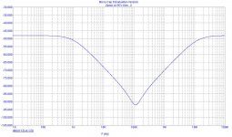
A little example of "fall" cap. tech.
A precedent circuits, but with "composite 1/2 caps": 50uF+25uF+10uF, no RC net.
More expensive tech. but more effective....
Ps: If you used this tech with a good "distribute R-L" PCB layout, the result it's more "linear"...
Ciao
Mauro
A precedent circuits, but with "composite 1/2 caps": 50uF+25uF+10uF, no RC net.
More expensive tech. but more effective....
Ps: If you used this tech with a good "distribute R-L" PCB layout, the result it's more "linear"...
Ciao
Mauro
Attachments
Mauro!
Great! And I just can't stand to jump in with some actual measurements that I have done some month ago [on th occasion of an another thread..]
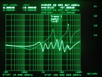
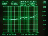
It's about the same "stepped" technique: At that time I wanted to show that it IS possible to do an effective bypassing, even with film caps, out to very high frequencies..
The result is shown here - please note the ! ~ -50dB !! level at 100MHz, with film caps, and at the same time no sky high resonance peaks. This all goes to -40db at 200 MHz - and is about the lowest value that I was able to produce up to now.. In the background, the second trace is some popular configuration.
But, in the same time I consider this thing just not sane, and very much impractical, it was just a crazy test to show the effectiveness of the capacitor stepping method.
The config is: 1000uF Panasonic // 1.5uF MKT // 1uF Mylar // 270nF MKT // 68nF mylar // 33nF stacked film // 6.8 nF mylar
And still it is non-optimized, only one thing that was assembled materials at hand. In practice similar stepping could be done with less parts better chosen.
Ciao, George
Great! And I just can't stand to jump in with some actual measurements that I have done some month ago [on th occasion of an another thread..]
It's about the same "stepped" technique: At that time I wanted to show that it IS possible to do an effective bypassing, even with film caps, out to very high frequencies..
The result is shown here - please note the ! ~ -50dB !! level at 100MHz, with film caps, and at the same time no sky high resonance peaks. This all goes to -40db at 200 MHz - and is about the lowest value that I was able to produce up to now.. In the background, the second trace is some popular configuration.
But, in the same time I consider this thing just not sane, and very much impractical, it was just a crazy test to show the effectiveness of the capacitor stepping method.
The config is: 1000uF Panasonic // 1.5uF MKT // 1uF Mylar // 270nF MKT // 68nF mylar // 33nF stacked film // 6.8 nF mylar
And still it is non-optimized, only one thing that was assembled materials at hand. In practice similar stepping could be done with less parts better chosen.
Ciao, George
Attachments
A further document that would like to illustrate an another application of this method: [and a good desdription]
http://www.irf.com/technical-info/appnotes/an-1081.pdf
Ciao, George
http://www.irf.com/technical-info/appnotes/an-1081.pdf
Ciao, George
Last thing:
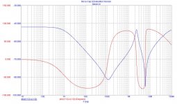
Mauro, your analysis of the pro-cons of the resistor damping is just precise. Though in practice you can achieve quite a good result. The curve here was shown already in a UCD thread, and config is: 470uF 63V // 47uF high ESR snubber // 100nF SMD ceramic +series damping .22 ohm
Mauro, your analysis of the pro-cons of the resistor damping is just precise. Though in practice you can achieve quite a good result. The curve here was shown already in a UCD thread, and config is: 470uF 63V // 47uF high ESR snubber // 100nF SMD ceramic +series damping .22 ohm
Attachments
Hi George,
Thanks for you "reality" confirm of my "elementary" description of this method.
This technique is fit for video or RF circuits, perhaps even for audio....
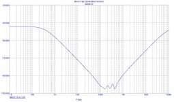
In connection with my graph, I have used a model of "good" ELcap as the Philips RSM37, and "good" filmcap ARCotronics R82.
I believe that is possible use the linearizing techniques, like as you have measured in the UDC PSU analyse.
The main point is the well study of the works points and the good components.
I wish I were there too study the effects of the phase linearity of the PSU on the sound, but to do serve it build a "linear" PSU.
The models that there are, "snubber" or "snubberless" am all little linear. The only method to try is:
1 use the "fall" or "stepped" technique (compensate)
2. linearizing the ELcap (big, mid and low value) with the resistors (serie), abdicating to they efficiency
Ciao
Mauro
Thanks for you "reality" confirm of my "elementary" description of this method.
This technique is fit for video or RF circuits, perhaps even for audio....
In connection with my graph, I have used a model of "good" ELcap as the Philips RSM37, and "good" filmcap ARCotronics R82.
I believe that is possible use the linearizing techniques, like as you have measured in the UDC PSU analyse.
The main point is the well study of the works points and the good components.
I wish I were there too study the effects of the phase linearity of the PSU on the sound, but to do serve it build a "linear" PSU.
The models that there are, "snubber" or "snubberless" am all little linear. The only method to try is:
1 use the "fall" or "stepped" technique (compensate)
2. linearizing the ELcap (big, mid and low value) with the resistors (serie), abdicating to they efficiency
Ciao
Mauro
Thank you both for the input.
It's interesting to see what happens if only SMD caps are used, very little inductance (looked at the irf document).
Can we make any conclusion about how it should look like if we take both impedance curves into accont and also the necessity of a snubber in the first place?
My idea now and also in the beginning is that you should concentrate your efforts close the supply pins if we talk LM3886 and otherwise close to the "power consumer" in general.
Mauro,
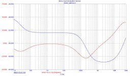
I don't really understand the low frequency part in this last graph. Could you please show also the according schematics?
Phase shift: I feel like the phase shifts produced by the power supply in a frequency range where there is still enough loop gain left to compensate for it, are getting compensated for by the amp. It becomes critical in the range where the phase margin of the amp diminishes, so it can not compensate any more, and can go actually in oscillation. Then, much above this frequency it does not count again, because though there is a bad phase shift, there is no more gain left for the oscillation requirement. For example, for an LM3875 I would say the "phase margin critical ramge" is the ~500K -1MHz range, as You know it just too well.
Else: I'm not too surprised by the agreement of your sims and my tests. You did make the right simulation with the right values, and that can be closer to reality than a fraction of dB! I've controlled that in the "another" forum 🙂
But it is [badly] needed to have the right parameters of the actual part in your hand!! And that is called a network analyzer..
And yes, this was just the marketing dep. blubber leading to a project:Your network analyzer on a shoestring [though only for the bravehearted]!!
http://n2pk.com/
A most beautiful one, seriously
Ciao, George
Per,
Yes, real HF [i mean RF] bypassing is done in the range of mm-s.. of the actual power circuit. These two things, short distance [minimal loop] and low rf impedance are unseparable.
Ciao, George
Yes, real HF [i mean RF] bypassing is done in the range of mm-s.. of the actual power circuit. These two things, short distance [minimal loop] and low rf impedance are unseparable.
Ciao, George
Hi peranders,
I have not details position on this diverged bypass techniques.
I believe that does it main point is analyse well the circuits and "only after" that is they have a concrete elements, are useful to modify to improve.
I believe that a PSU by OPamp is able is different by S.S. , but I don't believe that am great there differences " of method " among diverge OPamp or diverged PSU voltage or power.
The data and my doubts are here to look for a shareable idea on I don't know what to do about it a good PSU, with or without "snubber".
If you have ideas or data to add to my, perhaps we are able help the beginners to understand the problems of the audio PSUs...
SMD caps, ye, very low ESL, different resonance point , but equal principle of use ( and compensation ).
Perhaps the low Q of some types ( film ) in league with the low ESL is able improve the performances in the 100Khz-10Mhz zone.
I will do of the tests....
Ciao
Mauro
Hi George,
I share your analysis on the phase shift.
Some subjective elements make that is noticed in the forums, do me think that are even a phenomenon in league with the audio band, similar to the dynamicses it observes from Graham Maynard in his test " " inverse driven".
I have not done experiment directed to this phenomenon.
I believe that the better condition is that the phase of the PSU is identical in that of the amp circuit...
My Zener mod. circuit :
Attachments
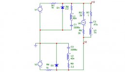
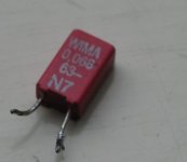
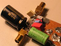
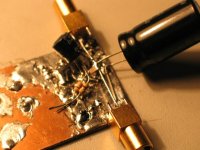
Bypass film cap:
Wima MKs02: p.2.5mm =~2-4nH ESL (George photo)
Arcotronics R82 p5mm =<7nH ESL (my ordinary use)
Wima MMC: SMD =~1-3nH ESL (good SMD implementations)
All Metallized polyester type, normalized Q ~ 3 - 7
Ciao
Mauro
Wima MKs02: p.2.5mm =~2-4nH ESL (George photo)
Arcotronics R82 p5mm =<7nH ESL (my ordinary use)
Wima MMC: SMD =~1-3nH ESL (good SMD implementations)
All Metallized polyester type, normalized Q ~ 3 - 7
Ciao
Mauro
Hi P-A,
If you are still watching this thread I have a newbie question:
In the schematics of your optimized supply (also in that of Carlos) there is a 100uF bypass cap before the final "snubber". What is the primary function of this cap? Ripple rejection or fast low-impedance energy storage close to the amp? I have some huge 100u Obbligato film caps (http://www.diyhifisupply.com/catalog/34/obbligatopsucaps) and I was wondering if they could be use here with any benefit (the supply is feeding a Hypex UcD module).
Thanks,
Nic
- Status
- Not open for further replies.
- Home
- Amplifiers
- Chip Amps
- Carlos' snubberized Gainclone Power supply, Part II