Interesting, but don't you get the upper NPN fighting with the lower PNP with high bias? Or, the upper PNP and lower NPN operating class-C? If you could offset the output as well as the input, then there would be no problem, but I see them connected together?

Actually I have exactly opposite experience both in the sims and in the real life. But of course, YMMV.That's the theory, but in practice removing the capacitor causes oscillations. This is confirmed by the loop analysis in sim: removing the cap kills the otherwise comfortable stability margins
And this is drawn from the solid theory, I'll try to find the book where this is explained and I first read about.
BTW, for the CFAs the value of the R12 resistor (according to your schematic) has some "optimum" value and all measurements of the CFA OPAmps in the datasheets are conducted with this value in mind.
I know the theory, and initially I used no capacitor, but looking at some working examples, I decided to try it.
It didn't make it by itself: other mod layers were necessary for stabilization, but it is an essential ingredient of stability (some of the other mods are probably not required, but they do no harm and I am a bit tired of reworking that thing: if it works in this condition, I'll leave it as it is).
Playing with the value of R12 is an option, but increasing it reduces the loop gain, meaning higher THD.
I do not need the relatively insane bandwidth of this amplifier, but reducing it also increases distortion at 1MHz
C4 produces a phantom zero. It usually improves stability when you use the right value, and degrades stability when you make it way too large.
Perhaps the right value C4 cancels one pole at the critical BWP frequency, but it may also move one LPT pole higher because the feedback network impedance is lower, in a similar way that an input filter cap does for the other (positive input) side. Some people use low value resistors for the feedback network to the same effect, but that requires higher power resistors. I like RC shunts on both feedback resistors, so the feedback network is low power and low impedance at RF frequencies.
But a cap in the C4 position exposes the LTP to RF from the speaker line, which is a common cause of RF rectification. The fix is a small resistor in series with C4.
This IPS is not an LTP but the same idea applies.
But a cap in the C4 position exposes the LTP to RF from the speaker line, which is a common cause of RF rectification. The fix is a small resistor in series with C4.
This IPS is not an LTP but the same idea applies.
Some excerpts from the Walt Jung's "OP Amp Application Handbook" concerning the CFB Amplifiers.


And note the assumption on the third image: Ro<<R1, Ro<<R2 which means that R1 cannot goes very low and hence additionally lowering the THD
And note the assumption on the third image: Ro<<R1, Ro<<R2 which means that R1 cannot goes very low and hence additionally lowering the THD
Feedback amplifiers with a lowish open-loop impedance at the negative side of the input stage were used decades before someone decided to abuse the term current feedback for it. Just look at a typical valve amplifier with feedback to the cathode of the input valve. They very often had a small capacitor across the feedback resistor.
These op-amps are designed to have a loop gain that drops off at a first-order rate until it is below 0 dB. In that case, a capacitor across the feedback resistor is unnecessary, and potentially harmful when it is too large. That's just a special case that doesn't necessarily apply to a custom-designed amplifier like Elvee's.
When the loop gain drops with a second-order slope or close to a second-order slope, a zero that kicks in an octave or so before the loop gain passes through 0 dB can help quite a lot.

Unfortunately, my amplifier was not aware of such previous developments, and it did whatever it wanted.Some excerpts from the Walt Jung's "OP Amp Application Handbook" concerning the CFB Amplifiers.
That's the reality. Guidelines and general principles are certainly useful, but up to a point: when they break down, you have to find your way by yourself, which I did, eventually, and the solution I found is certainly far from optimal, but it did work in the end.
I may try to refine it if I have the gusto to do it, but for the moment it remains my best bet.
Stability issues are among the most vexing and complex subjects, and every case is specific
The idea behind this compensation lies in voltage divider compensation known from oscilloscope probes.
Btw, do not underestimate phase lag of input differential pair - specially in case of no degeneration resistors.
Concerning hi-speed BD139/140 are not my first choice.
just my 2c
Btw, do not underestimate phase lag of input differential pair - specially in case of no degeneration resistors.
Concerning hi-speed BD139/140 are not my first choice.
just my 2c
Attachments
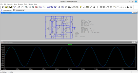
That's extreme class A! Almost 600mA of quiescent currentWhat do you think about this one?
agreeCheck out the circuit of the older Tek FG504 or similar function generators. They have a very linear output amp.
H&H describe this in detail in I think their 2nd Ed.
Jan
I checked, but the linearity is suited to a function generator, ie. good but not exceptional; well below my best variants anyway
I did buy a long time ago philips 1Ghz complementary power transistors bd139 style package, intended for function generator use.
you may need to go for high Ft transistors in allstages and the VAS stage plus cascoding, then apply cherry´s neested feedback techniques to create enough loopgain at 1Mhz.
you may need to go for high Ft transistors in allstages and the VAS stage plus cascoding, then apply cherry´s neested feedback techniques to create enough loopgain at 1Mhz.
Yes, it will be a one-off, as practically all my projects nowadaysHi Elvee, are you making only one proto of this design, by hand, on proto-board? Rick
I used RF power transistors for the OP, and the small signal transistors also have an Ft in the hundreds of MHz which should suffice hereI did buy a long time ago philips 1Ghz complementary power transistors bd139 style package, intended for function generator use.
Maybe one day ( when the snow falls) I'll have time to make a pcb of this design just for fun, assuming that you post the sim of the final design. It would be done in smt/tht to make it really compact 🙂Yes, it will be a one-off, as practically all my projects nowadays
Standard IC's are almost always limited to +/-15V supplies, but I need at least 24VDId you have a look at the LT1795 ADSL driver ? almost ticks the boxes..
- Home
- Amplifiers
- Solid State
- Can you improve these amplifiers?