Disconnect everything, leave the output only and check if still oscillates. Also screening each BJT could be helpful.
I would reduce the AC feedback to ~nothing and see what happens. Any oscillation would then be wiring, decoupling or proximity issues. Decoupling the signal path may be able to isolate problems but with two systemic paths, that is more work. I had an amp once where I had to put the miller cap directly on the VAS transistor to keep it from oscillating.
I have explored the circuit with a current sniffer as suggested by Marcel, but nothing clear emerges: the only place where a strong and clear signal is detected are the connections leading to the supply bypass caps, which is not surprising as they concentrate all the effects.
I have disconnected the OP stage and replaced the driving cascodes with 470 ohm resistors. It is stable by itself.
I connected the cascodes to the FB resistor, thus bypassing the OP: it was marginally unstable, with small "squegging" bursts.
This seems to indicate that the main problem lies in the front-end, and is amplified by the output.
I have equipped all the transistors with base and/or collector stoppers, and I have decoupled the OP supply from the rest with ferrite beds and a local bypass, but I didn't manage to kill the oscillations.
The values are not too aggressive, between 47 and 100ohm presently, I may need to go higher
I meant shielding when said "screening".Disconnect everything, leave the output only and check if still oscillates. Also screening each BJT could be helpful.
The collectors of the transistors are connected to the supply rails, which are ~equivalent to GND in AC terms, meaning they are mostly self-shielded, except for the base and emitter which are relatively minor regarding their electrical size.
I didn't manage to tame it (yet).
Maybe time to explore other options?
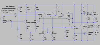
This is a first tentative, based on the AD797 topology. Components are mostly generic for the time being (sim).
It sort of works, but it is borderline regarding stability and slew-rate

Any comment?
Maybe time to explore other options?
This is a first tentative, based on the AD797 topology. Components are mostly generic for the time being (sim).
It sort of works, but it is borderline regarding stability and slew-rate
Any comment?
Attachments
I don't understand what Q7+D1 are for, so I tried removing it. Initially, I left Q7 collector connected and the THD improved, but when I removed it completely, the THD is worse. I found that a 1p1 cap has a similar current value but undistorted, and the THD is not improved. Then I used a diode instead of the Q7 collector and the improvement is back. The diode current is obviously got a lot of 2nd harmonic distortion, which must be cancelling something else?
Attachments
I suppose they bootstrap the lower CCS, to eliminate the Early effect. I lifted the circuit from the AD797 datasheet (it contains a description of the IC), but I added the diode to give the transistors a little more breathing spaceI don't understand what Q7+D1 are for, so I tried removing it
Ya but the first transistor in the current mirror has a single diode voltage on the collector so sans the emitter diode they are "balanced". I would put another diode in series with the current mirror bases so that both current mirror transistors have two diode voltage on them. I know, I should test/ simulate the idea before I say anything. 😉 later maybe
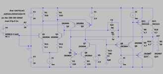
I finally managed to stabilize the amplifier, after adding layer upon layer of mods, stoppers, etc.
I don't know what exactly did it: stoppers, switching to non output inclusive compensation or other.
There are probably some mods that are totally irrelevant and others that collectively contribute to stability, but I am not going to investigate further as it would require to remove the mods one by one to determine which ones are really critical.
The stability is hard and strong: the squarewave response is immaculate, unlike the updated schematic:

A word about Q1 & Q2: the choice of 2N5551 and 2N5401 might seem strange, it would be more logical to use 2N2222 and 2N2907, but I noticed that the samples I had available (cheap Chinese types from Banggood) had half the collector capacitance of the Moto 2N's, and considering their location, it did matter.
As the dissipation was a bit excessive for TO92 devices, I designed a bespoke cooling clip to keep them safe
As the dissipation was a bit excessive for TO92 devices, I designed a bespoke cooling clip to keep them safe
I think C4 is unnecessary/harmful in this topology - this is CFA after all...
Also you can try to play with the R11, 12 values and trade-off THD for stability.
Also you can try to play with the R11, 12 values and trade-off THD for stability.
That's the theory, but in practice removing the capacitor causes oscillations. This is confirmed by the loop analysis in sim: removing the cap kills the otherwise comfortable stability marginsI think C4 is unnecessary/harmful in this topology - this is CFA after all...
In fact I was a bit lazy when I redrew the schematic: the resistors are not cascaded as shown, but paralleled from the driving side, going to each transistor individuallyIs R28 supposed to go to the base of Q20? Or to Q1c? Same issue on the other side for R29
Thought so 🙂 drawing error
It’s possible to lower the cross-over thd if you try Bob Cordell’s DoubleCross concept since you have a parallel push-pull class a-b ops. It’s described in his power amp design book second edition
It’s possible to lower the cross-over thd if you try Bob Cordell’s DoubleCross concept since you have a parallel push-pull class a-b ops. It’s described in his power amp design book second edition
- Home
- Amplifiers
- Solid State
- Can you improve these amplifiers?