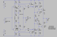
Sorry Elvee if it won't suit your application. It is flat response to 10 MHz and distortion is very low. You can increase the supply voltage so that you get the 15-0-15V output swing. This amplifier is built and working for almost the same purpose as you need, to amplify a signal generator output from 1 V. The input can be direct coupled to follow DC signal to 10 MHz. The main distortion component is at 4th harmonic and then only about 0.0012%. Using RF components wil probably get you to 100MHz.
Thanx for posting the simulation. I managed to stabilize it and fiddle a bit. R19 is not useful? You can trade off C3 with the value of added {rd} degen resistors to optimize the THD. Faster transistors may be a better idea? It helps stability to remove the collector resistors but will add heat to the follower transistors.
Attachments
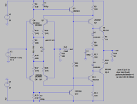
I did my homework regarding supply bypass, but I used a common reference for the cascodes: they are made of two Si diodes, but with a 470n ceramic bypass meaning chances of unwanted couplings are small.
I can try to separate them with an additional RC cell
I can try to separate them with an additional RC cell
Large amplitude, several volts and VHF: depending on the auxiliary caps, between ~50 and 150MHz.
It looks sine, but that's inevitable with my 100Mhz oscilloscope
It looks sine, but that's inevitable with my 100Mhz oscilloscope
I have tried isolation networks between the cascodes (330n ceramic + 56 ohm), but there is no significant change.
Stopper resistors look more promising, in the bases and collectors of some transistors, but pushing it too far would probably begin to impact the global loop stability
Stopper resistors look more promising, in the bases and collectors of some transistors, but pushing it too far would probably begin to impact the global loop stability
Maybe try some finger testing. Sometimes by touching certain parts of the circuit you can affect the amplitude of the oscillation. This can help to pinpoint the problem area and can also suggest a remedy.
Yes, I tried it but it seems relatively unresponsive: the only section where a sizeable effect is detectable is the output stage.
Pressing fingers there reduces the amplitude of oscillations and pushes them higher in frequency, both of which are good omens (generally).
However, I cannot kill the oscillations completely, and reproducing the finger effects with discrete components does not seem to work well.
I also tried to short node b directly to GND: it reduced the oscillations to an almost insignificant level, but it didn't kill them completely, meaning the problem is mostly local, just amplified by the closed loop conditions.
I suspect that the output stage behaves as two push-pull oscillators: they are RF power transistors, and because of the relatively large cooling clips of the TO5's, the area occupied is large and the length of the connections is not minimal
I assume you have seen this:
https://linearaudio.nl/winfield-hills-100w-10mhz-1000vus-amp-70
and the data sheet for the LT1360 is also interesting.
Note the inductors in the folded cascode, and the cascoded diamond IPS.
https://linearaudio.nl/winfield-hills-100w-10mhz-1000vus-amp-70
and the data sheet for the LT1360 is also interesting.
Note the inductors in the folded cascode, and the cascoded diamond IPS.
Given the frequency of oscillation and the results of your finger test, my money is on output stage parasitics. Did you try base stoppers, how about an output zobel? What about improving the HF decoupling there?Yes, I tried it but it seems relatively unresponsive: the only section where a sizeable effect is detectable is the output stage.
Pressing fingers there reduces the amplitude of oscillations and pushes them higher in frequency, both of which are good omens (generally).
However, I cannot kill the oscillations completely, and reproducing the finger effects with discrete components does not seem to work well.
I also tried to short node b directly to GND: it reduced the oscillations to an almost insignificant level, but it didn't kill them completely, meaning the problem is mostly local, just amplified by the closed loop conditions.
I suspect that the output stage behaves as two push-pull oscillators: they are RF power transistors, and because of the relatively large cooling clips of the TO5's, the area occupied is large and the length of the connections is not minimal
Philips used to have small ferrite beads (3x3.5 mm, grade 3B and 4B) that you can slide over the base pin of the transistor to damp oscillations.
Yes I have. I am not sure that it can achieve ppm THD at 1MHz though. The LT1360 can't either.I assume you have seen this:
Inductors in the cascodes probably avoid the shunting of the B-E dynamic resistance by the resistor, to scrape a little more HF gain, but I don't think they contribute to stability, the opposite might be true
I have tried base and collector stoppers, ferrite beads at various places, but not (yet) everything, everywhere at the same time.
As I said, I don't want to accumulate minor poles everywhere, as it could impact the global loop stability, but at this point I have nothing to lose and I may try it
As I said, I don't want to accumulate minor poles everywhere, as it could impact the global loop stability, but at this point I have nothing to lose and I may try it
I don't know if this helps, but when you take a 1:1 probe and connect the ground lead to the tip, you have a magnetic probe you can use to locate where the biggest oscillation currents are flowing.

- Home
- Amplifiers
- Solid State
- Can you improve these amplifiers?