That's second order. Yes, I know it doesn't look like it but it is. I was looking at the higher cross.
Are you referring to the woofer filter? I thought it was 1st order because I believed the two inductors, 1.5mH and 5.0mH, act as one 6.5mH.
Yes i understood that but thought the mid driver is only affected by the 1.5mH inductor and the woofer driver is affected by the combined total inductance of the two inductors making both filters 1st order. What am i missing?
Thanks
Thanks
In your case, I would suggest an impedance correction on each driver of approximately 7.5R and 15uF.
Middling case for a Kevlar driver. Not far off this SEAS CA18RLY paper driver.
http://www.seas.no/index.php?option...8rly&catid=44:utv-prestige-woofers&Itemid=461
This will lead to an entirely different circuit to B&W P6 2.5 way speaker. I don't want to go into it.
https://www.diyaudio.com/community/threads/flat-impedance-and-flat-power-response-design.302001/
Then add some optimal calculations. Thus.
Attachments
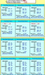
The only fixed voltage point in the woofer/mid combination is the amplifier. Shown here is a basic second order passive filter, note 180 degree phase...

No. Well, what are you trying to find out and why? What do you want to do? I applaud your striving for knowledge, that's how I got sucked into becoming a loudspeaker engineer. It is down a rabbit hole, the more you learn the more you realize "oh it is more complicated than what I thought!"would results be meaningful
As mentioned before, impedance is complex, and more complex than assumed in the early days of Thiele-Small modeling. Those labels "4 ohms" or "8 ohms" or whatever are the most oversimplified model, and often lied about these days (makers will put "8 ohms" to something that is really more like 4 because they don't want customers to say "oh I can't buy that my receiver is only 8 ohms"). You can see a typical curve for a woofer here https://audiojudgement.com/speaker-impedance-curve-explained/
- At the lowest frequencies, the impedance is dominated by the DC resistance of the voice coil, which is what your ohmmeter would measure presuming the driver is not connected to anything. (In other words you have to disconnect the crossover).
- As you move up in frequency goes up up up until you come to a peak which is the resonance of the driver, the impedance goes down down down until a flat part somewhat higher than the DC resistance.
- Eventually the impedance goes back up. This is NOT because the voice coil is like and inductor. That is kinda true but eddy currents in the magnetic pole pieces also. Usually you get a "semi-inductive" rise. When you see "inductance....XX mH" on a spec sheet that is usually at 1 kHz or something. It varies with frequency.

Yes i understood that but thought the mid driver is only affected by the 1.5mH inductor and the woofer driver is affected by the combined total inductance of the two inductors making both filters 1st order. What am i missing?
Thanks
I still would appreciate clarifcation on what order my mid and woofer filters are. The schematic in post #16 shows the LP and mid range only have inductors.
Thanks
Thanks
How many orders can you have with one inductor as LP for mid , and two inductors in series for a woofer?
This is a great forum and the very knowledgeable members have helped me learn some basic XO design considerations. As I learn more I'm sure there will be more questions. Basically I thought the woofer filter is 1st order because there are only two inductors in series, with no other components, and they are equivalent to one 6.5mH inductor.
Last edited:
Thanks. In your post 26 attachment I saw it was labled 2nd order and thought that was due to the resistors. So I think I now understand that any filter with two components is 2nd order. I thought that replacing two inductors with one inductor, equaling the combined value of L1 and L2, would result in an equivalent 1st order filter.
Last edited:
May I ask you to make a graph of this design, with frequency on the horizontal axis and sound pressure level at 1m distance from the front of the speaker on the vertical axis? And if you have done so, would you please explain why you drew the lines like you did?I really don't understand you reply. I know the woofer frequency is about 30 to 150Hz, mid range is 150 to 3000 Hz and tweeter is 3000 to 20kHz
Henry, that's not correct. RL filters require two components per order, so four for second order... that's two inductors and two speakers (speakers are passive components).
Last edited:
Now i'm really confused. So my woofer filter with only a 1.5mH and 5.0mH in series is not equivalent to a woofer filter with just one 6.5mH inductor
- Home
- Loudspeakers
- Multi-Way
- can speaker impedance be calculated