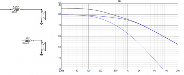
Before I was confused now I'm totally confused. So is the woofer seeing more or less inductance than the in series value of the 1.5mH L1 + 5.0mH L2?
This type of crossover would normally technically be called a "2.5 way", rather than a three way speaker.So is the inductance to the woofer not 6.5mH?
Your statement in post #12 that the "mid range is 150 to 3000 Hz" is incorrect, as both the bass drivers are seeing any and all low frequency signal applied to the +/- input.
The series inductance to the lower "helper" Cobex bass driver is indeed 6.5mH (1.5+5), the upper yellow driver, labeled "MF" in your "B&W P6 original crossover" diagram is a Kevlar cone "bass/midrange" with only 1.5mH in series, so it is not rolled off as low as the Cobex bass driver.
The "bass/midrange" does not have any high pass filter as would be required if it were a mid driver that was crossed over above a woofer.
The two parallel woofers would drop impedance to 3.5 ohms, probably at Fb (frequency of box tuning).
I'm curious whether the two woofers share the same chamber, or are separate?
If separate, there could also be two slightly different frequency Fb, though both speakers could have identical Fb even with different size chambers by adjusting port length in each box.
Art
Last edited:
No, it's a mess, and rather bizarre. Yes if the 5.0 and 1.5 were in series that would be 6.5 DEPENDING on their orientation to each other as there can be mutual coupling effects. However, the complex midrange impedance is in parallel between. So it's a mess...well not a mess necessarily in a bad sense, but very complicated.So is the inductance to the woofer not 6.5mH?
And NO the filters are really not first order. YES in theory an inductor in series with a resistor would be first order, and might be referred to as "first order." But the complex impedance of a woofer it is not at all going to behave like a textbook 1st order filter. Then when you consider the woofer response, the acoustic crossover is surely not first order at all.
Those terms "1st order" "2nd order" etc are best thought of as theoretical ideals from the world of electrical filters, just useful as a very rough idea of the crossover circuit, or maybe sometimes an actual acoustical target if designed from very sophisticated measurements and simulation.
The first inductor is in parallel with the mid driver from the perspective of the woofer circuit.The series inductance to the lower "helper" Cobex bass driver is indeed 6.5mH (1.5+5),
The woofer will not only roll off at a lower frequency than the mid, but it will be more steep.
There is a dependence on drivers and their impedance as has been mentioned.

thanks allenB. The speakers sound pretty good and maybe B&W knew what they were doing with such a simple XO. My main concern is that they don't use hi-end components so that was the reason I built the outboard XOs with what I thought were hi-end components.
Last edited:
Henry,
The orientation of the coils relative to each other or a speaker frame, or magnet can make a difference in their inductance and reactance. "Hi-end" components may have small differences in series resistance and other factors that affect the acoustic crossover response that may not always be for the better.
The box volume and tuning also affects the impedance curve of the bass drivers, which in turn affects the net acoustic crossover.
Still curious whether the two woofers share the same chamber, or are separate?
Art
Before I was confused now I'm totally confused. So is the woofer seeing more or less inductance than the in series value of the 1.5mH L1 + 5.0mH L2?
Without analyzing the circuit with Ohm's Law and complex numbers equations for series/parallel circuits (capacitive, inductive reactance), you can't understand where the voltage drops are and what current there passess. The same calculation will answer what the impedance of each part/branch is.
I'm aware of the importance good inductor orientation.Henry,
The orientation of the coils relative to each other or a speaker frame, or magnet can make a difference in their inductance and reactance. "Hi-end" components may have small differences in series resistance and other factors that affect the acoustic crossover response that may not always be for the better.
The box volume and tuning also affects the impedance curve of the bass drivers, which in turn affects the net acoustic crossover.
Still curious whether the two woofers share the same chamber, or are separate?
Art
I have a multimeter that can measure inductance, and it does something consistent across a speaker driver.
I usually get between 0.5 and 1.5mH. A speaker has 3-6R resistance too, so interpretation is difficult.
But didn't we have a go at improving the P6 speaker? Adjusted tweeter level and put a 4.7 or 5.6uF shunt across the mid:
https://www.diyaudio.com/community/threads/three-way-crossover-question.381399/page-2#post-6903042
Very long winded for such simple modifications, IMO. Standard B&W mod to reduce the midbass kevlar breakup. Been done before.
- Home
- Loudspeakers
- Multi-Way
- can speaker impedance be calculated