I’m trying to recreate the crossover used for the Electrovoice Patrician IV. I found a schematic of the crossover online (they’re potted) and this is it. Not shown in the crossover is a 16 ohm L-pad used on the midbass, tweeter, and super tweeter.

That “6 mH” inductor at the top that is in series with both the tweeter circuit and the 4.78 mH inductor for the midbass, someone pointed out that it made more sense for it to be a .6 mH. Which made more sense to me after doing the math, 0.6 would cross the tweeter to where it meets the super tweeter at 4250hz vs 425hz with 6 mH lol.
I drew it out to a form that helped me visually.

So I’m confused about the midbass circuit. Having a .6 mH in series with a 4.78 mH and then a 35.4 uF cap (two 17.7 uF in parallel as shown in the original schematic), wouldn’t that make the midbass play a band pass of just 280 Hz to 470 Hz, 6db slope? That’s a tiny amount of the spectrum. Am I understanding this correctly? All drivers being 16 ohm loads I’m seeing the high pass the 18” woofer at roughly 533 Hz, the midbass plays the same frequencies as the woofer at 280-470 (??? Doesn’t seem right).
Lastly, what inductors should I get. I’m thinking with a low pass of 533 hz on the woofer I can go with a large iron core. I have one here with a dcr of about 0.3 ohms. I need two 0.6 mH coils which I can go air coil. Not a lot of power will be going through these, the one in series with the tweeter go maybe 19-20 awg? The one in parallel with the super tweeter, 21-22 awg?
What about the other two 4.78 mH coils I need, the one in series with the midbass and one in parallel with the tweeter. Going with air core on those the coils will be unnecessarily huge, if I go with a thinner wire the dcr starts to rise and goes about the 5% of the Re rule (0.8 ohms in this instance). Should I go iron core on those? Or go air core, using like 20 awg and accept the higher dcr?
I have a decent collection of coils and have a good amount of magnet wire so I can wind my own air core, but have no issue just buying some iron core.

Example for the woofer circuit, I was just planning on taking this 5.9 mH iron core and taking it down to 4.78 mH. Looks to be 15-16 awg. But would love direction on what I can get away with as far as the inductors. I can’t see the need for an 18 awg 4.78 mH air core that weighs a few pounds being wired in parallel with the tweeter.

Thank you so much,
Dan
That “6 mH” inductor at the top that is in series with both the tweeter circuit and the 4.78 mH inductor for the midbass, someone pointed out that it made more sense for it to be a .6 mH. Which made more sense to me after doing the math, 0.6 would cross the tweeter to where it meets the super tweeter at 4250hz vs 425hz with 6 mH lol.
I drew it out to a form that helped me visually.
So I’m confused about the midbass circuit. Having a .6 mH in series with a 4.78 mH and then a 35.4 uF cap (two 17.7 uF in parallel as shown in the original schematic), wouldn’t that make the midbass play a band pass of just 280 Hz to 470 Hz, 6db slope? That’s a tiny amount of the spectrum. Am I understanding this correctly? All drivers being 16 ohm loads I’m seeing the high pass the 18” woofer at roughly 533 Hz, the midbass plays the same frequencies as the woofer at 280-470 (??? Doesn’t seem right).
Lastly, what inductors should I get. I’m thinking with a low pass of 533 hz on the woofer I can go with a large iron core. I have one here with a dcr of about 0.3 ohms. I need two 0.6 mH coils which I can go air coil. Not a lot of power will be going through these, the one in series with the tweeter go maybe 19-20 awg? The one in parallel with the super tweeter, 21-22 awg?
What about the other two 4.78 mH coils I need, the one in series with the midbass and one in parallel with the tweeter. Going with air core on those the coils will be unnecessarily huge, if I go with a thinner wire the dcr starts to rise and goes about the 5% of the Re rule (0.8 ohms in this instance). Should I go iron core on those? Or go air core, using like 20 awg and accept the higher dcr?
I have a decent collection of coils and have a good amount of magnet wire so I can wind my own air core, but have no issue just buying some iron core.
Example for the woofer circuit, I was just planning on taking this 5.9 mH iron core and taking it down to 4.78 mH. Looks to be 15-16 awg. But would love direction on what I can get away with as far as the inductors. I can’t see the need for an 18 awg 4.78 mH air core that weighs a few pounds being wired in parallel with the tweeter.
Thank you so much,
Dan
0.6mH does seem the more likely value. They will interact so it's not so simple to guess the result and you might want to simulate. The slopes will probably fall between 6dB and 12dB/oct.

Most of these crossovers are tailored by try and error simply based on real fr response of the drivers used. If you use other drivers, you need to adjust values.
0.6mH is the only way. Otherwise there would be almost no signal to upper mid/tweeter.
0.6mH is the only way. Otherwise there would be almost no signal to upper mid/tweeter.
17.7uF? 4.78uH? What kind of values are those anyway? Why the spurious accuracy, they are not E12/24/48/96/192 even... I guess a very old design?
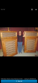
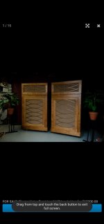
The drivers being used are the originals from the Patrician IV. Basically I’m helping this older couple. The husband built this speaker years ago, like 60s or so and was never able to get a crossover. He’s had them for all these years and he’s never heard the speaker he built. So his wife asked if I could help, the original crossovers are spendy. I figured I could get the a decent crossover made up for about a fifth of what the originals sell for. Thank you for confirming the .6 mH.Most of these crossovers are tailored by try and error simply based on real fr response of the drivers used. If you use other drivers, you need to adjust values.
0.6mH is the only way. Otherwise there would be almost no signal to upper mid/tweeter.
17.7uF? 4.78uH? What kind of values are those anyway? Why the spurious accuracy, they are not E12/24/48/96/192 even... I guess a very old design?
Yes, super odd values used in this crossover. It is indeed an old design, very old design. If someone wants to quickly whip up a superior crossover please do lol. I’m not stuck on this crossover, I just want to give them something that will sound good and I figured I can’t go wrong with the original design.
Dan
This crossover network is definitely custom designed for specific drivers and their FR's.
With that 6mH issue solved as .6mH, it needs to be realized for the values to make sense -
the woofer is actually 8 ohms (not 16). The rest are 16 ohms. With that realized the C/O frequencies are roughly :
Woofer = 250Hz
Mid/Bass = 270Hz & 600Hz
Tweeter (so called) = 700Hz & 4Khz
Super Tweeter = 4Khz.
(as you can see, there are obviously response/impedance of driver issues as variance)
Last edited:
Trying for a new crossover, where the owner is accustomed to the existing one, is risky. You could do significant measurement, but you won't progress just using expensive parts and you won't manage it using theoretical values.
The alternative to standard measurement practices would be a lengthy adjustment period. You might use an equaliser and listen, trying to 'fix' the problems you hear. What can't be fixed may need crossover adjustment instead.
After that, proper placement and equalisation and mode treatment in the final listening room.
I think EV built a crossover with the parts they had plenty of. Looking at the scheme my first thought was: why all these identical values? But that is pretty ridiculous. Now my guess is the posted scheme, obviously being old, could be wrong. Where did you get it?
Is it this monstrosity?
Attachments

I think the problem is the 3 sig figs of precision. 4.78mH is only 0.4% away from a more reasonable 2 sig fig value of 4.8mH. Are they really suggesting that the inductors need to be wound to 0.4% tolerance?4.78 milli Henry.
17.7 micro Farad.
Vintage labels.
Why so confused Mark?
Don't trust EV?
Hello
As far as the series woofer inductor I don't see why you can't unwind the larger coil. DCR won't be critical unless it goes high and adds loss. You have trim pots on all other drivers so as long as you don't seriously attenuate the woofer it shouldn't matter. It's not like a notch filter where DCR can effect Q so you have to look at R + DCR to model the effect.
Good luck and cool speaker to be working with.
Rob 🙂
This crossover network is definitely custom designed for specific drivers and their FR's.
With that 6mH issue solved as .6mH, it needs to be realized for the values to make sense -
the woofer is actually 8 ohms (not 16). The rest are 16 ohms. With that realized the C/O frequencies are roughly :
Woofer = 250Hz
Mid/Bass = 270Hz & 600Hz
Tweeter (so called) = 700Hz & 4Khz
Super Tweeter = 4Khz.
(as you can see, there are obviously response/impedance of driver issues as variance)
Thank you for that, makes much more sense. I had just read that all the drivers were 16 ohm, but clearly not the woofer.
Trying for a new crossover, where the owner is accustomed to the existing one, is risky. You could do significant measurement, but you won't progress just using expensive parts and you won't manage it using theoretical values.
The alternative to standard measurement practices would be a lengthy adjustment period. You might use an equaliser and listen, trying to 'fix' the problems you hear. What can't be fixed may need crossover adjustment instead.
After that, proper placement and equalisation and mode treatment in the final listening room.
Well that’s the thing, they are accustomed to nothing. Unfortunately the husband is fairly old and from what I understand didn’t remember what he had built. So I was just going to put something simple together so that he could at least hear it before his time is up. After some help I found out what the speaker really is (it was built as a mono setup). So figured might as well go with what was meant for it.
I think EV built a crossover with the parts they had plenty of. Looking at the scheme my first thought was: why all these identical values? But that is pretty ridiculous. Now my guess is the posted scheme, obviously being old, could be wrong. Where did you get it?
I got it from EV documentation.
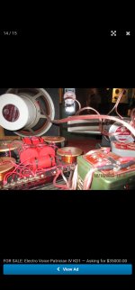
Here is an image of the original crossover.
Lol, that is indeed it, a huge horn, he got the kit though. Home built, clearly the one in your photo there has had an updated crossover. Here is his actual speaker, needs dusted out of course. Odd that he’s hauled it from home to home for the last 60ish years and has never heard it.Is it this monstrosity?
So what about the 4.78 mH inductors on the tweeter and the midbass circuits? Should I use a smaller iron core on those or go air core, but use like 20 awg wire?
Dan
Thank you very much! Any thoughts on the other coils? That’s what’s stumping me. I have a second one of those 5.9 mH coils, should I just do the same to it for the midbass drivers? Then wind something for the tweeter using smaller wire (20-21 awg)? Being across the tweeter I can imagine it only seeing maybe 20 watts max or so. ImHello
As far as the series woofer inductor I don't see why you can't unwind the larger coil. DCR won't be critical unless it goes high and adds loss. You have trim pots on all other drivers so as long as you don't seriously attenuate the woofer it shouldn't matter. It's not like a notch filter where DCR can effect Q so you have to look at R + DCR to model the effect.
Good luck and cool speaker to be working with.
Rob 🙂
Pretty sure the plan is to use an amplifier only capable of 50 watts on it, for now. Not sure about future use, but I’m guessing this thing can sing on a couple of watts.
Dan
The crossover you showed, if it's for the same drivers and cabinet, will lead to your most efficient result. It sims OK, despite what it looks like.I was just going to put something simple together
This one is not so expensive, and it comes with +/_3% tolerance. Personally, i would not bother to unwind it for 4.8mH.
https://www.parts-express.com/Dayton-Audio-IC185-5.0mH-18-AWG-Laminated-Iron-Core-Inductor-257-668
https://www.parts-express.com/Dayton-Audio-IC185-5.0mH-18-AWG-Laminated-Iron-Core-Inductor-257-668
Thank you very much! Any thoughts on the other coils? That’s what’s stumping me. I have a second one of those 5.9 mH coils, should I just do the same to it for the midbass drivers? Then wind something for the tweeter using smaller wire (20-21 awg)? Being across the tweeter I can imagine it only seeing maybe 20 watts max or so. Im
Pretty sure the plan is to use an amplifier only capable of 50 watts on it, for now. Not sure about future use, but I’m guessing this thing can sing on a couple of watts.
Dan
Hello Dan
You have some serious history there! I agree on the power as they are how old??? 50 watts was a big amp back then so I would be cautious power wise as the drivers are obviously NLA and if in good shape as in never used are probably going to surprise you and the builder.
I think your are right I doubt they would need much power. My dad had an altec 12" 601 coax that had a tweeter that used a microphone diaphragm as the tweeter, 3000 I think very delicate. It sung using the headphone output of his radio.
That lower midrange dual compression driver is really unique! Those are compression drivers so they will roll off naturally anyway. I would do the same thing initially with the inductor and see what you get. Even if it's not ideal can't hurt as long as the DCR is reasonable.
Yes I would like you said keep to the schematic and KIS. Just put it together and see what you get.
Your lucky to be setting up a really nice vintage system!
Rob 🙂
This one is not so expensive, and it comes with +/_3% tolerance. Personally, i would not bother to unwind it for 4.8mH.
https://www.parts-express.com/Dayton-Audio-IC185-5.0mH-18-AWG-Laminated-Iron-Core-Inductor-257-668
Are you saying that you’d use that iron core for the tweeter and midbass circuits?
Dan
What are you talking about? It was already established many times there is 0.6mH inductor in parallel to tweeter.
Better starting write that zero before dot.
Better starting write that zero before dot.
- Home
- Loudspeakers
- Multi-Way
- Can someone help me understand this 4 way crossover and help with selecting the inductors?