HI everyone!
I could use a little help with the calving buffer I have implemented.
While everything seems to work correctly, during start up, it draws about 200-300mA.
While this is not an issue with any series regulated supply, it poses a problem with my shunt supply that has a current limit at about 80mA.
I set the bias for the output device at about 25-30mA but due to this inrus, the bottom rail takes several several seconds to reach the targeted rail (+/-24V).
I have also observed, once the rail reached 24V target, the bias current stays at 50-60mA for about 30-40s before going suddenly down to the targeted 25mA. I have scoped the output and there is no oscilaltion.
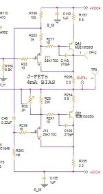
I am including here the schematic for reference.
Any suggestions is very welcomed!
I could use a little help with the calving buffer I have implemented.
While everything seems to work correctly, during start up, it draws about 200-300mA.
While this is not an issue with any series regulated supply, it poses a problem with my shunt supply that has a current limit at about 80mA.
I set the bias for the output device at about 25-30mA but due to this inrus, the bottom rail takes several several seconds to reach the targeted rail (+/-24V).
I have also observed, once the rail reached 24V target, the bias current stays at 50-60mA for about 30-40s before going suddenly down to the targeted 25mA. I have scoped the output and there is no oscilaltion.
I am including here the schematic for reference.
Any suggestions is very welcomed!
Attachments

Might be a little to much voltage for Drain/Source
Might even latch up if any gate leakage.
Not sure to analyze it much further.
CFP with a Fet and BJT seems like a thermal nightmare.
And assume without modeling would need more bias for such voltages.
Trying not to sound negative. Doesn't seem like a very feasible
circuit for the application.
Might even latch up if any gate leakage.
Not sure to analyze it much further.
CFP with a Fet and BJT seems like a thermal nightmare.
And assume without modeling would need more bias for such voltages.
Trying not to sound negative. Doesn't seem like a very feasible
circuit for the application.
Thank you for your response these are very good feedbacks. R168 in the full circuit is used as feedback to lower OLG. I can try today to disconnect it and see if the problem disappears, or it stays.Is the problem still there when you disconnect before R168? Could it be that the input voltage is non-zero when powering up?
Furthermore, I will try to make sure to monitor if the input voltage is not negative during power up. The buffer is in the feedback loop, I can also try to remove it from it and see if the problem still persists.
I will post updates tonight.
I monitored it and there is no oscillation at any point in time. I had the same thought as you, but the circuit is stable. Let me re-scope it to make sure and I will post updates tonight.I think you need to post the full circuit if you want any good advice. Does sound a bit like oscillation that dies out, but it could also just be things warming up if there's no temperature control on the bias.
White dragon, not sure why I cannot quote you, it makes things a bit more difficult, you might want to check settings on your profile to allow people to link you.
By not enough bias, you mean on J11/13 or on Q43/51? I have roughly 5mA on the Jfets and 25-30mA on the output devices.
By not enough bias, you mean on J11/13 or on Q43/51? I have roughly 5mA on the Jfets and 25-30mA on the output devices.
I have just noticed now that I can quote you, so maybe the problem was on my end, sorry!Might be a little to much voltage for Drain/Source
Might even latch up if any gate leakage.
Not sure to analyze it much further.
CFP with a Fet and BJT seems like a thermal nightmare.
And assume without modeling would need more bias for such voltages.
Trying not to sound negative. Doesn't seem like a very feasible
circuit for the application.
Also regarding too much DS voltage on the Jfet, given the rails are +/-24V and that the LSK170 are rated for 40V, the part won't see voltages over the breakdown voltage until the input won't go over about 18V roughly. Perhaps a good idea will be to limit the rail voltage for that down to 22V. However, in practice, it is impossible to reach those voltage levels during any normal use of the preamp. I can't quite wrap my head around this issue.
As I said earlier, this evening I will conduct more experiments and I will post updates.
Last edited:
I have performed several experiments tonight. First off, I have removed the buffer from the complete circuit to isolate the issue by disconnecting one end of R22 and connecting it to a signal generator.Is the problem still there when you disconnect before R168? Could it be that the input voltage is non-zero when powering up?
Unfortunately, the problem was still consistent with my early findings, i.e. the buffer seems to have a large in-rush current.
I have therefore worked on all biasing for the circuit to make sure to not incur into any abnormal operating point, For that I have removed the trim pot and increased the resistors R245/255/197/206 to 15ohm. This sets the biasing for J11/13 to around 3.4mA (these J-Fet have been selected with a lower IDSS of about 6mA) and biasing for Q43/51 to about 20mA.
Even though this improved the square wave response to a rather clean response, I also played with R217/241 by trying different values from 0 to -1K to understand if the BJT was indeed clearly operating in linear mode. As expected, as I am increasing the base resistor, the bandwidth of the buffer decreases, but there is no improvement with the inrush current.
I have measured the current going through R28 and for the base resistor R241. For several seconds, I have 1.85V across R28 and about whopping 2mA going through the base of Q51,
It seems as if the current spike is due to the Jfet initial current running to the max Idss and I am not sure why and how I can have 2mA at the base given that the hfe for this device is a min of 100 and the shunt can only supply about 70mA.
Also worth mentioning, I confirm, there is no oscillation at any point during start up that causes this behavior. The reason why it takes several seconds to start up and causes an issue with the output offset, is because it is powered by the shunt that can only provide less 70mA.
Tomorrow I will build this circuit on the breadboard which will make easier testing different solutions including different output devices (Perhaps using a BJT with higher hfe might help?!),
I know you have wide experience with this buffer for the Paradise project, and know more than me, would you please be so kind to double check if you have a prototype for this buffer, if you also detect this current spike at start up?
Any suggestions will be very welcomed!
I was rather thinking to keep it in place, but disconnect the input. R168 should keep the input voltage to the Calvin buffer to zero. That way, there should be no DC offset at turn-on so everything should power up "normally". I am suspecting some kind of latch-up situation, which then goes away by the components heating up and changing their parameters, but there is not enough measurement data to support this suspection......Thank you for your response these are very good feedbacks. R168 in the full circuit is used as feedback to lower OLG. I can try today to disconnect it and see if the problem disappears, or it stays.
Furthermore, I will try to make sure to monitor if the input voltage is not negative during power up. The buffer is in the feedback loop, I can also try to remove it from it and see if the problem still persists.
I will post updates tonight.
correct, R169 sets input reference to ground, but I have removed the buffer from the rest of the circuit to isolate the issue. Unfortunately, as you have read, I didn't succeed in tagging the issue yet.I was rather thinking to keep it in place, but disconnect the input. R168 should keep the input voltage to the Calvin buffer to zero. That way, there should be no DC offset at turn-on so everything should power up "normally". I am suspecting some kind of latch-up situation, which tcalvin Buffer you can hen goes away by the components heating up and changing their parameters, but there is not enough measurement data to support this suspection......
I will build the buffer on a breadboard and I will take scope shots of the start up current on both rails and post. Do you have a Calvin buffer you could kindly double check for me? I might chase a problem that cannot be fixed and always been there but never observed perhaps?
I haven't read all posts, but after looking the circuit topology I note, two things:HI everyone!
I could use a little help with the calving buffer I have implemented.
While everything seems to work correctly, during start up, it draws about 200-300mA.
While this is not an issue with any series regulated supply, it poses a problem with my shunt supply that has a current limit at about 80mA.
I set the bias for the output device at about 25-30mA but due to this inrush, the bottom rail takes several several seconds to reach the targeted rail (+/-24V).
I have also observed, once the rail reached 24V target, the bias current stays at 50-60mA for about 30-40s before going suddenly down to the targeted 25mA. I have scoped the output and there is no oscillation.
I am including here the schematic for reference.
Any suggestions is very welcomed!
1) there are no information concerning the load. Are the mentioned value from 200-300mA also present after switch on without load ?
2) there are jFET's in use. In off-mode and during start up (immediately after switch on) jFETs in general are usually self conducting - actually a wire between drain and source (when there is zero voltage between its gate and source terminals).
I guess, this is the main reason for 200-300mA after switch on.
Thanks for your response.
1) the behavior is identical with and without load. Also keep in mind the load is given by the positive biasing of the output devices
2) You are indeed correct, at start up they act like a short with max ID= IDSS which is what I see. Unfortunately, the high current event lasts for several seconds (15-20s) so I tend to attribute it to a different phenomenon perhaps?
If this was the behavior for such a popular buffer, I am sure that people would have notice that, considering it is used on the DIY Paradise phono stage if I recall correctly, and it's powered with a Shunt supply as well. Since I cannot find anything related to anybody complaining or observing this, I have to conclude the problem is isolated to my case. This is why I am asking Hesener if he can double check on his prototype.
Another interesting aspect, is that, only the negative rail takes time to ramp up, the positive doesn't and comes up immediately.
I don't use fancy shunt regulators for every circuit.
Actually I don't use them at all.
We have had huge oscillations with the F5 headamp with some shunt regulators.
Change to simple cap multiplier, everything is fine.
Different regulators have different frequency response and stability with complex load.
Patrick
Actually I don't use them at all.
We have had huge oscillations with the F5 headamp with some shunt regulators.
Change to simple cap multiplier, everything is fine.
Different regulators have different frequency response and stability with complex load.
Patrick
Last edited:
Hi Patrick, good to hear from you! Still owe you some answers...... not forgotten!
Yes, shunt regulators can be painful, and I use cap multipliers a lot. The "Paradise" phono really was a joint work of multiple people, with Joachim Gerhard doing the concept, Michael Borresen did the circuit, Frans der Wal did the regulators, and I just did the PCB layout and group buy. And Calvin (Christoph) later contributed the Calvin buffer, which is a big improvement over the original output buffer. The shunt reg proved to be difficult in multiple builds, when people changed transistors mostly, and it could take some time to find out.....
In this case however, I think that it could be a case of the Base-Collector junction being forward biased (since the neg supply doesnt come up), and the circuit just seems to like that new bias point a bit too much..... But we will see.
@ stefanoo, usually the calvin buffer is well-behaved and I had it up and running easily in several other projects as well, without this problem. I may still have my prototype somewhere, and will try if I can make it do the same thing when I limit the startup current...... Not sure when I will get to that.....
Not sure why you would have oscillation, especially if layout is done properly and you have taken care of the proper compensation poles.
While I cannot comment on the F5, I can comment on this, and can state I have no oscillation during start up not after.
Secondly Paradise, which is a very popular DIY project, uses shunt regulator to power up the circuit which many capable people have vetted out carefully, this is why I am asking if this issue was known, because:
a) if it was, I can see if something was done to prevent it and/or if there no way to fix it.
b) if nobody has noticed this and this is a problem with the choice of my bias point and/or output device.
Regarding your cap multiplier, I need to study to understand how this can help with the start up, since the problem is current starvation ff the shunt device.
Last, what do you mean who is to blame? hmmm....I am not blaming anybody...here just to see if I can get some ideas as how to solve it.
Anyway, if anybody has this prototype available on hand and can also check if it has the same behavior as mine and can share findings would be very appreciated,
Unfortunately, I made all the boards already otherwise, I would go for a Jung series regulator to power the buffer.
Thank you so much for your answer. I feel much better knowing you don't have this problem, which means I can resolve it without having to intervene with cuts and jumps on the PCB.Hi Patrick, good to hear from you! Still owe you some answers...... not forgotten!
Yes, shunt regulators can be painful, and I use cap multipliers a lot. The "Paradise" phono really was a joint work of multiple people, with Joachim Gerhard doing the concept, Michael Borresen did the circuit, Frans der Wal did the regulators, and I just did the PCB layout and group buy. And Calvin (Christoph) later contributed the Calvin buffer, which is a big improvement over the original output buffer. The shunt reg proved to be difficult in multiple builds, when people changed transistors mostly, and it could take some time to find out.....
In this case however, I think that it could be a case of the Base-Collector junction being forward biased (since the neg supply doesnt come up), and the circuit just seems to like that new bias point a bit too much..... But we will see.
@ stefanoo, usually the calvin buffer is well-behaved and I had it up and running easily in several other projects as well, without this problem. I may still have my prototype somewhere, and will try if I can make it do the same thing when I limit the startup current...... Not sure when I will get to that.....
I do appreciate you can look into this on your prototype. I will in the meantime breadboard it and take scope shots on the startup current and document everything here.
(maybe if you can just post the exact parts and value you used for your build I will replicate it on the breadboard, this could be a good starting point to assess the issue I am experiencing)
Thanks everyone for chiming in and give me good ideas.
Thank you for chiming in. We could arguably say the PSU is underrated. I say arguably since it is a shunt supply and the inrus current is measured tonight in the neighborhood of 200mA. Given the peak current, shunt supply cannot be sized for that amount, unless you allow for a much larger footprint.
Also on the same token, 200mA shunt supply would be a waste for a 20-30mA buffer.
Also on the same token, 200mA shunt supply would be a waste for a 20-30mA buffer.
- Home
- Amplifiers
- Solid State
- Calvin buffer large inrush current