Thanks you two, those are both good ideas. I could do tinitus' idea and keep trying and I could always cut out the back of the cabinet in the coax triangle but if I do wouldn't I have to worry about wavelength cancellation (presuming a low cut off) if I do that? That is why I was asking about the holes idea. Set me straight here.
If those holes are small and very few, you got a high tuning vented box.
If you drill a lot of holes, then it become more and more like open back.
And I think it'd be not so intereting in between them🙁
I once played with a guitar driver in an open back cabinet. It sounded resonant to me🙁
If you drill a lot of holes, then it become more and more like open back.
And I think it'd be not so intereting in between them🙁
I once played with a guitar driver in an open back cabinet. It sounded resonant to me🙁
ok so I kinda like the idea of a bunch of 1" holes. Is it wise to start with say 10 holes and increase it if there is still a boxy sound or am I barking up the wrong tree?
the origin of multiple small holes is very old
and supposedly the origin of todays more "advanced" aperiodic
I think you will need to cover the holes with felt, or some other acoustic material
and supposedly the origin of todays more "advanced" aperiodic
I think you will need to cover the holes with felt, or some other acoustic material
The "holey" idea is going to get you an aperiodic tuning. That's probably a good thing. You can vary the amount and thickness of the stuffing over the holes to change tuning.
If you have a way to measure the impedance you can check this by looking at the impedance curve.
Scanspeak and Dynaudio used to make a Variovent for this sort of thing.
If you have a way to measure the impedance you can check this by looking at the impedance curve.
Scanspeak and Dynaudio used to make a Variovent for this sort of thing.
I've read somewhere that...
The holes in the back should be equal to baffle thickness ,and the total "blank"area equal to Sd ; internal volume should be lightly stuffed and something more transparent than felt should be used ,and glued near the holes. Also an additional protective grille on the outside could be posed to maintain everything firm .
The holes in the back should be equal to baffle thickness ,and the total "blank"area equal to Sd ; internal volume should be lightly stuffed and something more transparent than felt should be used ,and glued near the holes. Also an additional protective grille on the outside could be posed to maintain everything firm .
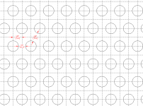
OK so if the 3/4" hole (same as baffle) is the right size and I follow Dave's suggestion of a 3:5 spacing ratio, that's 44 0.75" holes. That's gonna take up a big part of that triangle.
Thanks to all for the input so far.
Thanks to all for the input so far.
Those 44 3/4" holes will give you a surface area of about 19.5 sq. in. About 25% of the driver Sd. Surprising, isn't it?
Yessorry you're right Pano ... I've read the wrong Chapter 😱
Should be half or less drivers' Sd . Also a reduction of chamber volume if the response overtakes the woofer response , may be done .
Should be half or less drivers' Sd . Also a reduction of chamber volume if the response overtakes the woofer response , may be done .
Oops. I forgot the R part of PR^2. Each hole is .44 in^2. The cone is about 78 if you subtract the spider around the horn. I'm gonna wear out my speed bit. 😀
Actually I might just try a few less knowing I can add more as needed. So, to be clear on my extrapolation, a 3/4 hole on a 1 1/4" grid means there is 1/2" between them?
Actually I might just try a few less knowing I can add more as needed. So, to be clear on my extrapolation, a 3/4 hole on a 1 1/4" grid means there is 1/2" between them?
We were typing at the same time.
OK, that more like it.
OK, that's easy to do but I don't think that will be a problem, this will be fully active.
Should be half or less drivers' Sd .
OK, that more like it.
Also a reduction of chamber volume if the response overtakes the woofer response , may be done .
OK, that's easy to do but I don't think that will be a problem, this will be fully active.
So, to be clear on my extrapolation, a 3/4 hole on a 1 1/4" grid means there is 1/2" between them?
Attachments
Nice😀
All those seem to share the same hole size, so you might try the coax placed in the middle to form a WWTWW with all W on a curve and surround the coax😀

I second the WWTWW design, it will look better balanced & "probably" sound better that way as well essentially imitating a point source like Dunlavy & Montana speakers do, no?
Edited Comment: Sorry posted my response before knowing the cabinet was already built...
Thetubeguy1954 (Tom Scata)
=========================================================
"The man that hath no music in himself nor is not moved with concord of
sweet sounds is fit for treasons, stratagems and spoils."
- William Shakespeare
Last edited:
I like Dave's hole diagram. Very soothing to look at, for some reason.
Maybe I've been staring at too much drywall lately...
Maybe I've been staring at too much drywall lately...
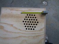
Looking Good !
Hey Cal it's looking good, starting to come together don't you just love when a plan comes together. 😀
Great Job ! Looking forward to your observations !
Hey Cal it's looking good, starting to come together don't you just love when a plan comes together. 😀
Great Job ! Looking forward to your observations !
Splits are on the other side, and I saw one from here 😛
LOL
Seriously, they look good. And I'm wondering, what if overlaying another perforated board on this one (by a gap)?
Better damping (higher loss)? Or that's not necessary since the damping material inside will do the job.
LOL
Seriously, they look good. And I'm wondering, what if overlaying another perforated board on this one (by a gap)?
Better damping (higher loss)? Or that's not necessary since the damping material inside will do the job.
- Status
- Not open for further replies.
- Home
- Loudspeakers
- Multi-Way
- Cal's next venture