So I’m not finding clear information on this. Is it calculated by turns from center tap to plate tap? Or by impedance from center tap to plate tap? Say one had a transformer with 100 turns, then a center tap, then 100 more turns to the other plate. 40% ultra linear would be tapped at turn 40 from the plate end, i.e. center tap, 60 turns, UL tap, then 40 more turns?
thanks in advance!
thanks in advance!
Hello Anchorman:
"Say one had a transformer with 100 turns, then a center tap, then 100 more turns to the other plate"
You are describing a 50% centre tap with this scenario.
"40% ultra linear would be tapped at turn 40 from the plate end," yes and the next section would be 60 to the other end.
I hope this helps
"Say one had a transformer with 100 turns, then a center tap, then 100 more turns to the other plate"
You are describing a 50% centre tap with this scenario.
"40% ultra linear would be tapped at turn 40 from the plate end," yes and the next section would be 60 to the other end.
I hope this helps
Ultra linear percentage represents amount of anode signal delivered to g2.
If you have 100 turns from center tap to anode, then 40% ultra linear is at 40 turns from center tap.
If you have 100 turns from center tap to anode, then 40% ultra linear is at 40 turns from center tap.
It is viewed as a feedback percentage: 0% means no AC signal on the anode is fed back to g2 (pure pentode operation). 100% means all the anode AC signal is fed back to g2 (pure triode operation). UL is in between.
so calculating by turns/voltage is correct. This makes the math much easier too 🙂It is viewed as a feedback percentage: 0% means no AC signal on the anode is fed back to g2 (pure pentode operation). 100% means all the anode AC signal is fed back to g2 (pure triode operation). UL is in between.
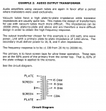
Ultra Linear
The calculation of percent is identical for both push pull, and for single ended.
It is a measure of the turns from B+ to the screen, versus from B+ to the plate, expressed as a percent.
Example:
1000 turns from B+ to plate; 1000 turns is 100%
400 turns from B+ to screen; 400 turns is 40%
Why do I list B+ to plate, 1000 turns as 100%
That is because Triode wired pentodes and Triode wired beam power tubes are "100% UL"
(if you wish to think of it that way, or can look at it that way, sort of a 100% Ultra Linear circuit).
The higher the percent number, the lower the plate impedance, rp, is.
The higher the percent number, the lower the gain from g1 to plate is.
However, for a specific tube type, True Ultra Linear is a particular percentage.
Some tubes are true ultra linear at 40%, others are true ultra linear at 26%, etc.
That is because true ultra linear has an optimum percentage for a given tube type to get the lowest distortion.
There are documents that talk about the optimum percent versus tube type more precisely.
“That is because true ultra linear has an optimum percentage for a given tube type to get the lowest distortion.
There are documents that talk about the optimum percent versus tube type more precisely.”
Nice explanation 6A3sUMMER. Why is it the case that “true ultra linear has an optimum percentage for a given tube type to get the lowest distortion“? Is it a function of tube geometry? Reference to docs would be appreciated.
“That is because true ultra linear has an optimum percentage for a given tube type to get the lowest distortion.
There are documents that talk about the optimum percent versus tube type more precisely.”
Nice explanation 6A3sUMMER. Why is it the case that “true ultra linear has an optimum percentage for a given tube type to get the lowest distortion“? Is it a function of tube geometry? Reference to docs would be appreciated.
It's a function of the geometry/spacing of the individual tube elements, along with the electrical parameters (voltage, current, etc) of the chosen operating point, and how all of those things interact. I can't point you toward any particular documents to back this up, but it's the basic fundamentals of how tubes work. Someone wiser may be able to explain clearly why the spacing of the grid and screen elements effects, and the voltages applied will effect the shape of the curves, and the overall linearity of the tube's ability to amplify a signal.
There are a number of threads that give links to UL.
They have details on the effects on distortion (harmonic and intermodulation), and output power, versus tube type and UL tap percentage.
I did not save any of those links, sorry.
If I remember correctly, jhstewart9 has posted much good information, graphs, schematics, and links on several threads here in Tubes / Valves.
These two statements are mutually contradictory. The signal proportion is determined by the impedance ratio, which is the square of the turns ratio.Ultra linear percentage represents amount of anode signal delivered to g2.
If you have 100 turns from center tap to anode, then 40% ultra linear is at 40 turns from center tap.
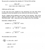
No, its not by impedance. See screenshots from 2 pages from Wolpert's book.It's by impedance.
Attachments
As I just mentioned in another thread Patrick's website can still be accessed on the web archive. ( archive.org and turneraudio.com.au ) I copied his website to my local drive. Great guy, had some great correspondence on cathode feedback with him just before he passed away.
Another great website is pearl-hifi.com unfortunately the website will sooner or later disappear. Emails do not get replied to - I contacted his daughter and he has moved and shut the business down.
Another great website is pearl-hifi.com unfortunately the website will sooner or later disappear. Emails do not get replied to - I contacted his daughter and he has moved and shut the business down.
Fortunately, Patrick's website has been preserved at the Internet Archive (aka "The Wayback Machine"). Here is the last snapshot taken before the site was taken down.I saved excellent tutorial from Patrick's Turner web site (now permanently offline because great author passed away).
https://web.archive.org/web/20220121171042/http://www.turneraudio.com.au/
Although both are related, of course, calculating by voltage/turns ratio makes most sense, because it IS one particular case of voltage feedback, here applied to screen which IS a voltage control grid too (ever heard of screen drive?), and was found to improve linearity.
Using impedance here is not wrong but clumsy, there is no "power" involved (if anything, very low one) and to be ofany use must be back converted to voltage, so ....
Using impedance here is not wrong but clumsy, there is no "power" involved (if anything, very low one) and to be ofany use must be back converted to voltage, so ....
Since the 1960s, I've always heard it specced as a turns ratio. The actualy impedance is meaningless?
The "optimum" is very broad, and depends on if you want a bit more power or a bit less THD.
The "optimum" is very broad, and depends on if you want a bit more power or a bit less THD.
- Home
- Amplifiers
- Tubes / Valves
- Calculating ultra linear taps on transformer