The voltage ratio in a transformer is related to turn ratio , not reflected impedance which is "virtual" and variable with secondary load , not a fixed resistor .
That would imply than if you use 4ohm speakers insted of 8 ohm you change the ultralinear ratio ...
That would imply than if you use 4ohm speakers insted of 8 ohm you change the ultralinear ratio ...
Last edited:
1. Test your ultra linear transformers:
(unloaded)
SE transformer: Connect a signal generator from the plate to the B+, measure the plate to B+ voltage (V1), measure the B+ to screen voltage (V2). 100 x (V2/V1) = Ultra Linear Tap Percent.
Push pull transformer: Connect a signal generator from one plate to the center tap (V1), measure the plate to center tap voltage (V1), measure the center tap to screen voltage (V2). 100 x (V2/V1) = Ultra Linear Tap Percent.
Then, Repeat for plate #2, and screen #2.
Or, push pull transformer method two (quicker and easier):
Connect the generator from plate to plate (center tap not at DC ground, not at AC ground).
Measure plate to plate voltage (V1). Measure screen tap to screen tap voltage (V2).
100 x (V2/V1) = Ultra Linear Tap Percent.
Turns Ratio is the key to the number of percent.
2. Ultra Linear has sometimes been called "Distributed Load". I consider this to be an optimist's view point.
Consider a 40% UL tap. 0.4 turns versus 1.0 turns = 16% impedance versus 100% impedance
50mA of plate signal current, versus 50mA of screen signal current (of course the screen signal current swing will not equal the plate current swing). More likely, the plate will vary by 50mA while the screen is varying by perhaps 30mA.
But even if the plate and screen signal current swings were able to be equal . . .
(50mA plate current swing squared) x 100% impedance has lots of power out.
(50mA screen current swing squared) x 16% impedance has very little power out.
Distributed load? . . . Yes, if you consider plate power to be more than 6 times the screen power that is delivered in Ultra Linear.
Just my opinion.
Most contributors in this thread wrote that "ultra linear ratio" is a turns/voltage ratio of the primary and some backed this up with (references to) literature.The voltage ratio in a transformer is related to turn ratio , not reflected impedance which is "virtual" and variable with secondary load , not a fixed resistor .
That would imply than if you use 4ohm speakers insted of 8 ohm you change the ultralinear ratio ...
If this is indeed the meaning of "ultra linear ratio" (which I believe it to be) than how can a change from 8 to 4 Ohm as the secondary load change the turns/voltage ratio of the primary? As far as I understand, the "ultra linear ratio" is the same for both the 8 Ohm and the 4 Ohm secondary load because there is no change of the turns/voltage ratio of the primary itself.
Most important for me: knowing that when a design calls for 40% ultra-linear taps, they're talking about the turns ratio on the transformer, not the impedance ratio. The rest is important, but as they say, "academic".
Pentode / Beam Power wired mode: 0% Tap
Ultra Linear wired mode: somewhere between 1% and 99% Tap
Triode wired mode: 100% Tap
Just a silly way to look at it.
With no negative feedback, the tradeoffs are:
Gain
Plate resistance, rp
Distortion
Damping factor
Output power
Global Negative Feedback changes these
Ultra Linear wired mode: somewhere between 1% and 99% Tap
Triode wired mode: 100% Tap
Just a silly way to look at it.
With no negative feedback, the tradeoffs are:
Gain
Plate resistance, rp
Distortion
Damping factor
Output power
Global Negative Feedback changes these
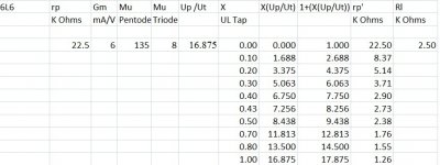
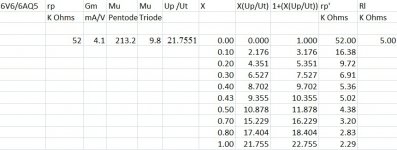
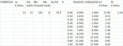
More data showing that the common 43% tap is not always the best. Rudolf Moers has more documentation on this that is even more detailed with lot of theory added but most of it is covered in these two documents. I found the results for the el84 interesting.
Using a zener between the UL tap and screen (as I mentioned in the past) changes matters too....
Using a zener between the UL tap and screen (as I mentioned in the past) changes matters too....
Attachments
EL506,
Thank you for these excellent excerpts of mr. Moers book. They essentially answered my questions in post #9 nicely. This convinced me that I have to own it and I am going to buy it now. If I can just figure out where to get it. Looks like ordering it from the Netherlands?
I did not see mention of “Using a zener between the UL tap and screen changes matters” in the book excerpts as I quickly scanned them. Did I miss it? Could you please restate and explain about the effect of Zeners used in this manner, other than the obvious lowering of screen voltage and thus screen current?
Hi! Can you share this archive in ZIP format for example? I will upload it to my web site. Wayback machine archive is very slow.As I just mentioned in another thread Patrick's website can still be accessed on the web archive. ( archive.org and turneraudio.com.au ) I copied his website to my local drive. Great guy, had some great correspondence on cathode feedback with him just before he passed away.
Another great website is pearl-hifi.com unfortunately the website will sooner or later disappear. Emails do not get replied to - I contacted his daughter and he has moved and shut the business down.
In most Ultra Linear transformer circuits, the output tube(s) screen voltage is larger than their plate voltage.
From B+ to 40% screen tap, the DCR x (plate + screen current) = medium voltage drop. High screen voltage.
From B+ to 100% plate tap, the DCR x plate current = an an additional and larger voltage drop. Lower plate voltage.
Perhaps the Only reason for a zener in series from the UL tap to the screen is to make the screen voltage equal to or lower than, the plate voltage.
Given the lower screen voltage, if you want to have the same plate current:
You have to either use less fixed bias voltage,
Or,
You have to reduce the resistance of the self bias resistor.
And . . . lower bias voltage makes the job of the driver tube an easier job, for Class A1 and AB1 operation.
Just my theory of what they are trying to accomplish with the zener.
- Home
- Amplifiers
- Tubes / Valves
- Calculating ultra linear taps on transformer