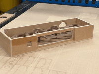
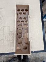
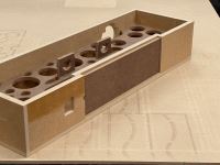
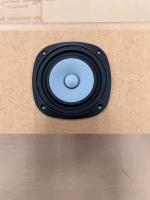
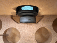
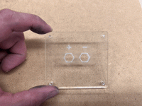
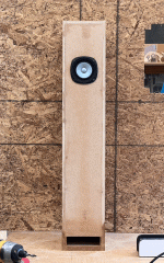
Dry fitting is going well. There are only a few small issues that would have been solved with having a finish pass when cutting. Next up is to finish drilling the holes where the 1/8" bit was too short to cut all the way through, then glue everything together. I also need to find my stash of binding posts, so that I can make the board for that. Then time for a listen 🙂
Thanks for the help so far! I'm hoping that I don't like these so much that I feel the need to buy some of the more $$$ drivers and build a bigger set. I have two more of these drivers, and was considering maybe a set of the Baby-Lab Skyflash, a set of basic ported boxes, and maybe a dipole mini-tower. It would be nice to have a whole bunch of different cabinets with the same driver to get a feel for what makes each type shine in it's own way.
Thanks for the help so far! I'm hoping that I don't like these so much that I feel the need to buy some of the more $$$ drivers and build a bigger set. I have two more of these drivers, and was considering maybe a set of the Baby-Lab Skyflash, a set of basic ported boxes, and maybe a dipole mini-tower. It would be nice to have a whole bunch of different cabinets with the same driver to get a feel for what makes each type shine in it's own way.
Attachments
When I learned how to use the CNC router, it was a game changer for building pretty much everything. It takes longer to draw everything up, but you can work out a whole bunch of the build problems without wasting any wood. The program I use allows for parametric design, so if you draw something up correctly from the start, you type in a number and poof, the material thickness, and everything related to that changes, while leaving things like the inside dimensions as defined. If you get good at figuring out tolerances, it's pretty much one and done with very little sanding or fitting.
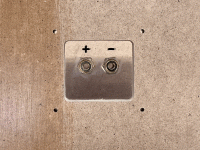
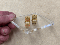
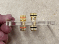
Found some binding posts I got last year from the auction site, and cut some 1/4" thick acrylic with a laser cutter to mount them. A little acrylic paint or some wax pencil rubbed into the etched +/- symbols makes them a bit more legible. I'll was thinking about tapping threads into the acrylic, but it doesn't make very strong threads. Some parts of the cabinets are glued up, but I usually take my time with glue-ups, so that everything stays well aligned, and held square and tight.
Attachments
for basic modeling of solid objects, and making toolpaths for the CNC router, I use Fusion 360 for the most part. For sending things to the laser cutter, either autocad or adobe illustrator. Sometimes a mix of those, depending on what I am trying to do, since one might excel at something the other doesn't do well.
@anchorman thank you sir. I've been putting it off for too long. Fusion 360 is my next major hurdle. If you happen to have any tutorials that you recommend, I'd very much appreciate it.
I got some glue on a surface that wasn't supposed to get glue yet, so I went ahead and clamped the whole thing together. Almost ran out of clamps!
Using polyurethane glue can be a blessing and a curse... it has a longish open time, but if you don't clamp every single surface well, it will puff up and push the pieces apart and make a weak joint. As a wise man once said, "too much is never enough", and that certainly holds true for clamps. 😆
Hopefully the second box goes together a little more smoothly!
Attachments
@anchorman thank you sir. I've been putting it off for too long. Fusion 360 is my next major hurdle. If you happen to have any tutorials that you recommend, I'd very much appreciate it.
I started with this youtube video from autodesk. There are a lot of changes since 2009, but for the most part, it's good information that shows a proper workflow using parametric design. You can work with solids for the most part, but I like to use the sketch function to draw my parts, and extrude the solids from the sketches. It's important to understand the way the constraints work in the drawings, and also that you can't make joints between bodies, only between components (which can contain bodies amongst other things). There are good help instructions inside of fusion, and usually hovering over something with your mouse will bring up a brief explanation. I came to the drafting/drawing side of fusion from mostly using illustrator, and it didn't make sense to me at first, but now I use it to draw just about everything, even quick sketches for things I'm going to make exclusively with hand tools.
@anchorman thank you sir. I've been putting it off for too long. Fusion 360 is my next major hurdle. If you happen to have any tutorials that you recommend, I'd very much appreciate it.
somehow the video didn't link before.
box number one complete and stuffed. Sounds pretty good, but I'm i the middle of a large concrete room. I think it will be better when I get them home and can place closer to a wall. Temporary wall made of a piece of OSB behind the speaker definitely helps the sound. It's surprising that a little speaker like this can actually make some feeling of bass notes, even when not driven very loud. #2 is getting glued now in a couple of stages to minimize stress trying to clamp it all.
Attachments
Got both built and located closer to a wall. Really nice. It’s hard to believe that those little drivers are actually making bass that I can feel in addition to hear… currently listening to Rahsaan Roland Kirk. Time to look at building a pair of these with some bigger drivers like the CHP-90, or CHN-110 🙂
And one of these days I need to finally make my twin towers… I was wanting to try them with these CHN-70 drivers, but I think the boxes would end up way too big…
And one of these days I need to finally make my twin towers… I was wanting to try them with these CHN-70 drivers, but I think the boxes would end up way too big…
At moderate listening levels it’s very satisfying nonetheless. the cone is only moving about 1mm or so. But I can still feel it. It might be my office located behind the speakers is creating a resonating chamber or something? It’s. The shop I work is a weird space, not exactly ideal listening conditions, but it sounds pretty nice all the same.
Might get away with 3-4 liter space for the drivers in an array. Not so much bigger than the wesayso twin towers… I should get some more of these drivers, regardless 🙂
Anyway, thanks to Scott and Dave for this sweet design for the Pensil speakers. Very satisfying build and listening!
I finally figured out how to use Hornresp to make a model of this... Seems to work? I modeled with 4 segments, since I couldn't figure out how to make the transition to the slot otherwise. Is there a way to do that more elegantly? I basically made segment 3 have .1 cm length, and then had the 4th segment the area of the mouth and thickness of the board. Added 12 oz of fill to the model, and it's amazing how much it smooths out the response curve in the model. I can't remember if I ran these at all with no stuffing, so can't compare the sound. I also haven't gotten around to measuring the FR of the actual boxes. Mark Audio says not to run test signals for some 100+ hours. Is it really necessary to do that in order to protect the drivers from damage?
That's the correct way. (Either that or I've been doing it wrong!)I modeled with 4 segments, since I couldn't figure out how to make the transition to the slot otherwise. ... I basically made segment 3 have .1 cm length, and then had the 4th segment the area of the mouth and thickness of the board.
I modeled with 4 segments, since I couldn't figure out how to make the transition to the slot otherwise. Is there a way to do that more elegantly?
Hornresp can model a Pensil loudspeaker three different ways. The results are effectively the same for all three models.
(The Path length is the distance between the centre points of the two outputs in the actual physical design).
Model 1 - Segment 3 transition
Model 2 - Stepped segments
Model 3 - Offset port (with no end correction)
- Home
- Loudspeakers
- Full Range
- calculating Pensil speaker dimensions for arbitrary drivers
