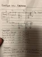
As i posted earlier, the word is that the tweeter now has a 15uF cap and a 0,1uF Jupiter Copper Foil bypass cap (used to be 20uF and 0,22uF Jupiter Copper Foil). It is hard to see in the pictures, but the 7mH inductor is on the opposite side. Could the third cap be the 20uF connected to the woofer circuit?
But that still doesn't explain the extra resistor. Would this have big impact on the sound quality? Wonder why they increased the cost of manufacturing all of a sudden?
But that still doesn't explain the extra resistor. Would this have big impact on the sound quality? Wonder why they increased the cost of manufacturing all of a sudden?
Chemarcelo, before you give up on the Caladan speakers, please try these few small modifications. According to my calculations, the Dayton tweeter must have the same polarity as the woofers ! So, no inverted polarity on the tweeter ! I know that sounds counterintuitive, but you lose nothing if try that. The second modification is that the inductance (L1) in parallel with the Dayton tweeter should be 0.5 mH, not 1.25 mH as stated in the crossover schematics. When you apply these two modifications, the sound should improve significantly for the better.I have to share your findings. I was also disappointed at the sound of my Caladan clones and Ron is a paid reviewer like most of them. Lesson learned.
I knew it! The tweeter coil is the only part that i haven't got 100% confirmed since Clayton pours resin around the parts. Although I know that it's almost impossible to determine the value of a coil from the size of it, I always felt that 1.25mH probably was a bit much.Chemarcelo, before you give up on the Caladan speakers, please try these few small modifications. According to my calculations, the Dayton tweeter must have the same polarity as the woofers ! So, no inverted polarity on the tweeter ! I know that sounds counterintuitive, but you lose nothing if try that. The second modification is that the inductance (L1) in parallel with the Dayton tweeter should be 0.5 mH, not 1.25 mH as stated in the crossover schematics. When you apply these two modifications, the sound should improve significantly for the better.
I'm clearly no expert, but what does the inverted polarity actually do?
I have started my Caladan build but haven't ordered the parts for the crossovers yet. Maybe my procrastination will pay off after all?
Hi Davorito,Chemarcelo, before you give up on the Caladan speakers, please try these few small modifications. According to my calculations, the Dayton tweeter must have the same polarity as the woofers ! So, no inverted polarity on the tweeter ! I know that sounds counterintuitive, but you lose nothing if try that. The second modification is that the inductance (L1) in parallel with the Dayton tweeter should be 0.5 mH, not 1.25 mH as stated in the crossover schematics. When you apply these two modifications, the sound should improve significantly for the better.
Thank you so much for the feedback. I'm glad you took the time to improve the project. I hope the people that are going to try it would benefit from it. Like I said a while back, I was a little disapointed from all the work and money that I invested in the project. So, I sold my Caladans a while back.
King30, and provably many others, are asking what are we talking about? Here is the crossover I was working from. Just remember, this XO needs to be modified, as Davorito suggested. Thank you all.
