"This 300B settings is foolproof, the driver is separated by capacitor"
Is simply not true and therefore i tried to find a good explanation...
Is simply not true and therefore i tried to find a good explanation...
Even in this case -where the schematic is contains higher grid leak resistor, than recommended- the good 300B is in safe mode, the dissipation is below the 80% of maximum.
If the tube is healthy, no significant grid current via the -larger- grid leak resistor, which would move the grid potential to such direction (relative to cathode) where tube overdissipating.
If the tube is healthy, no significant grid current via the -larger- grid leak resistor, which would move the grid potential to such direction (relative to cathode) where tube overdissipating.
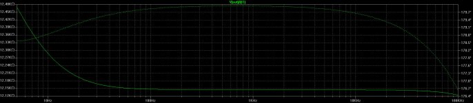
Just re. the pentode driver stage (output impedance, etc.) from the article as food for thought:
"In many ways this Amplifier could be called the "ultimate" WECO 91. While investigating the old WECO design I noticed many things, but one thing that stood out was simply how much lower the distortion from a correctly designed penthode driverstage is. The drawback is that in the old WECO design the very high output impedance of the Driverstage causes HF rolloff and poor delivery. In the Legacy the WE310 driver valve is replaced with a much meatier EL84 (or indeed as I did later with a Siemens C3m). This allows a output impedance of the driverstage that is by the factor ten lower than in the original WECO design and that can deliver more than eight times the current.
The driverstage with around 16mA operating current provides enough current to avoid slewing into the 300B grid for over 500kHz Bandwidth and is in conjunction with the output impedance and the 300B input capacitance naturally limited to 190kHz, so the driverstage will under NO conditions run into slewing. The not inconsiderable grid current of the 300B on peaks can also be accommodated, allowing better power delivery. Essentially, the Driverstage on this Amplifier is not the limiting factor both with regards to bandwidth and linearity."
...the pentode driver stage (output impedance, etc.)...
Simulated:
Attachments
Your simulations are worthless. You presented a couple of strikingly ugly designs in the other thread.
Biasing always matters. What would be an appropriate level of plate current and anode voltage, plate dissipation taken into consideration? A high but not excessive current, maybe at the expense of anode voltage, without abuse.
Your simulations are worthless. You presented a couple of strikingly ugly designs in the other thread.
I suggest you paying some attention to your communication skills. 😎
Loading not taken into account, simulation data are of no value. Instead of the high impedance active plate load (CCS), a low plate resistor value also provides more effective force transmission (impedance matching).
Armed only with Ohm’s law, you won`t get very far and the fictitious representation method is nothing more than a deceptive game.
How much plate current would a 220 Ohm cathode resistor give us?
How much plate current would a 220 Ohm cathode resistor give us?
Hello,
On the levacy you must have equal current in each 1/2 6AS7 and it is possible only by try different tube.
I made a 300b amplifier with triode C3g last year. For good swing and low distortion 24 k plate load is good.
For PSU regulate SIC MOS is better than 6AS7, very low out impedance and no hum.
On the levacy you must have equal current in each 1/2 6AS7 and it is possible only by try different tube.
I made a 300b amplifier with triode C3g last year. For good swing and low distortion 24 k plate load is good.
For PSU regulate SIC MOS is better than 6AS7, very low out impedance and no hum.
Hi Eba
Thanks for this. Do you have a schematic of your C3g amp that you could share?
Many thanks
Thanks for this. Do you have a schematic of your C3g amp that you could share?
Many thanks
Hi Basslink,
Yes I have, but I will doing some correction. And it's a French shematic yet.
Yes I have, but I will doing some correction. And it's a French shematic yet.
Last edited:
Ah, French electricity. I understand the problem. I am blessed with Google translate who is mon ami joyeux et serviable.
Disco,
No because M101 is a high power SIC MOS, I wrote 14 W on the schematic . This amplifier run since one year is very stable.
There is a mistake, in first time I tried EC8010, the voltage bias C3G is 2,8v.
No because M101 is a high power SIC MOS, I wrote 14 W on the schematic . This amplifier run since one year is very stable.
There is a mistake, in first time I tried EC8010, the voltage bias C3G is 2,8v.

- Home
- Amplifiers
- Tubes / Valves
- C3m 300b SET question