no never one like this.
a freind is going to purchase some 18 sound drivers as replacement in some eaw SB850.
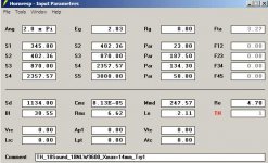
we haven't decided , if we buy the cheaper 18lw 2400 or the 18nlw9600(c)
when he puchased them,i'm gone bild a test box like that to see if this works(and for fun) 🙂
the design needs some fine tuning
its modeled the "cubo" way
why do you think it doesnt work(wel)?
a freind is going to purchase some 18 sound drivers as replacement in some eaw SB850.
we haven't decided , if we buy the cheaper 18lw 2400 or the 18nlw9600(c)
when he puchased them,i'm gone bild a test box like that to see if this works(and for fun) 🙂
the design needs some fine tuning
its modeled the "cubo" way
why do you think it doesnt work(wel)?
Last edited:
For software it doesn’t make a difference (besides the volume difference) how the driver is positioned but in reality it does make a difference. I also wonder how the driver will behave under high power in such situation. It wouldn’t surprise me to see the LF drop as part of saturation effect and thermal power compression. These were the reasons for turning the drivers ‘upside down’ in manifolds during the 80ties.
no never one like this.
a freind is going to purchase some 18 sound drivers as replacement in some eaw SB850.
we haven't decided , if we buy the cheaper 18lw 2400 or the 18nlw9600(c)
when he puchased them,i'm gone bild a test box like that to see if this works(and for fun) 🙂
the design needs some fine tuning
its modeled the "cubo" way
why do you think it doesnt work(wel)?
Hey EPA,
Already working on the new speakers i see. 😛
Whe have made the dission to go for the 18 Sound 18NLW9600. The carbon version is not available before the end of august. I just dont think the 18LW2400 is good enough for the job. ( Whe want inprove, not just replace ) Im still not shure if whe will do them one by one or a compleet set at once. I'll keep u posted on the status.
lol hoi tomHey EPA,
Already working on the new speakers i see. 😛
Whe have made the dission to go for the 18 Sound 18NLW9600. The carbon version is not available before the end of august. I just dont think the 18LW2400 is good enough for the job. ( Whe want inprove, not just replace ) Im still not shure if whe will do them one by one or a compleet set at once. I'll keep u posted on the status.

good to know .
now i have something to work with.
the 9600 needs a smaller beginning.
already worked on that.
im not sure what you mean by"saturation effect"For software it doesn’t make a difference (besides the volume difference) how the driver is positioned but in reality it does make a difference. I also wonder how the driver will behave under high power in such situation. It wouldn’t surprise me to see the LF drop as part of saturation effect and thermal power compression. These were the reasons for turning the drivers ‘upside down’ in manifolds during the 80ties.
does the heat dissapation would'nt be the same as in a br box?
already worked on the same model with the speaker reversed .
the tc volume wil be less,and you gain a bit in s4
Last edited:


And this is based on what, information from RSL in Breda?I just dont think the 18LW2400 is good enough for the job. ( Whe want inprove, not just replace )
Saturation is maybe not the best word but if the pressure in your first compartment becomes to high the mass of the air drops which results in less efficiency.im not sure what you mean by"saturation effect" does the heat dissapation would'nt be the same as in a br box? already worked on the same model with the speaker reversed . the tc volume wil be less,and you gain a bit in s4
As far as heat, during the eighties a lot of research has been done (and published) by David Carlson and David Gunnes from Electro Voice. In manifolds the cooling was about 20% to 30% better when the drivers were flipped around. The heat dissipation in your design is definitely not the same as in a basreflex. Sound pressure is not the same as airflow.
18NLW9600 - Post #265
Hi epa,
You are increasing the thermal resistance in the cooling path for the driver quite strongly by mounting the driver inside a relatively small box. On the positive side, this should be very easy to measure in a box like yours where you can install the driver both ways.
I like the looks of your 3d in Post #265, but I can't see any advantage in locating the mouths in the center of the cabinets. Anyway, here is another Hornresp model for the 18NLW9600:
Regards,
Attachments
hi oliver
the idea behind the symetric approach is for gradiant or even broadside array's
in the example above you wil get a wider horizontal an narrower vertical beam as you stack more subs vertical.
or flip the bottem sub 180 (when use 3 on a floor)with fase reversed and delayed(i know it needs fancy filtering)
but also with endfire it helps to be symetric,
if one is using only 1 or 2 subs it is not necessary to make them symatric agreed
"...the idea behind the symetric approach is for gradiant or even broadside array's..."
Hi epa,
I figured you were after something like that. Your example's output is restricted below app. 90Hz, so you're looking at wavelength longer than about 4m. I'm just suggesting that concentrating on the optimum internal acoustic layout and power handling capabilities is more important.
Regards,
Hi epa,
I figured you were after something like that. Your example's output is restricted below app. 90Hz, so you're looking at wavelength longer than about 4m. I'm just suggesting that concentrating on the optimum internal acoustic layout and power handling capabilities is more important.
Regards,
Epa, why don't you use the clever folding style similar to your earlier designs (from your post # 5 for example)? That type of folding will have a perfect radiation horizontal or vertical, the opening is centred, strongest construction(less panel-flex) and it has the best cooling capabilities.the idea behind the symetric approach is for gradiant or even broadside array's
Last edited:
hi oliver.
i agree for broadside setup you wil need a stack of six on the floor ,or 12 in front of the stage ,to get 2/3 wl of 32 hz
yes i am a dreamer😛
looking @ the model, from the plan it seams a verry tight space the magnet is in,but perpendicular it has the the whole width of the box.
plus air is moving fastest back and forth at that point.
and it is a 48 ltr volume.
but once we bild te test model,we wil be monitoring temps.
btw i was thinkin to bild something to measure excursion , using an old optical mouse and a barcode glued to the dustcap.
going to experiment tomorow a bit with that(if i can find one laying around)🙄
erik
Hi epa,
I agree with Djim, your layout from Post #5 is very promising (even though a little difficult to get worked out), and it has the added advantage to eliminate the L12 distance by directly feeding the throat of the horn, which more often than not seems to model better. It takes a little more wood, but it should stack nicely. I suggest you start with that general design, a square mouthed S5 straight into the rear of the driver, and fold the rear from there. I would suggest to run most of the fold parallel to the L45 centerline, that way you can easily tune the length.
"...once we bild the test model,we wil be monitoring temps..."
Even without arguing over how much air flow there really is inside a throat chamber, you have to look at the transfer of heat from the voice coil to the ambient air. By design you are heating up the air in the throat chamber, and that heat has to be transferred out of that space for normal cooling to be able to take place (finned aluminum side walls anyone?). You are looking at trying to maintain the largest possible temperature difference between driver and surrounding air. If you do any heat testing, do some testing over the normal range of usage hours to account for build-up.
The excursion measurement setup sounds intriguing.
Regards,
A fan works great and it was actually an option for earlier 18Sound 9000 series, you would almost wonder why 😀By design you are heating up the air in the throat chamber, and that heat has to be transferred out of that space for normal cooling to be able to take place (finned aluminum side walls anyone?). You are looking at trying to maintain the largest possible temperature difference between driver and surrounding air. If you do any heat testing, do some testing over the normal range of usage hours to account for build-up.
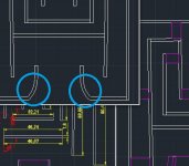
For example if you take 90 Hz as max upper wavelength (straight sections can be max 1/6 of the WL) that would be about 64cm max.And how might it sound (or model in hornresp) if the pieces (I've circled) are straight angles instead of curved?
Last edited:
Symmetrical layout
Hi epa,
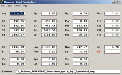
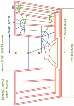
Here is a second try work product of a symmetrical layout with the 18NLW9600. First I made the drawing from a Hornresp simulation, then I took the attached Hornresp input from the drawing, both can be improved.
Just food for thought, as always, the devil would be in the details.
Regards,
Hi epa,
Here is a second try work product of a symmetrical layout with the 18NLW9600. First I made the drawing from a Hornresp simulation, then I took the attached Hornresp input from the drawing, both can be improved.
Just food for thought, as always, the devil would be in the details.
Regards,
Attachments
Last edited:
hi oliver
i like that aproach of your latest.
especialy the longer s4>s5 wil help lf extension.
i wil explore it later this week.
for now a sandwich,an a schrewdriver to open the mouse i found
i like that aproach of your latest.
especialy the longer s4>s5 wil help lf extension.
i wil explore it later this week.
for now a sandwich,an a schrewdriver to open the mouse i found
depending on how many pieces you make them,it doesnt make much difference,just be careful to not restrict the hornpath .And how might it sound (or model in hornresp) if the pieces (I've circled) are straight angles instead of curved?
fi. if you make the bend 2 straight pieces it wil work fine.
Oliver, I have some suggestion for your drawing. Because of the deep position of the driver it is maybe more comfortable to make the driver mountable from the back. Also an extra sheet on the back is no luxury in case 18NLW9600c is used.
For easy outlining the first section of the horn I would choose parallel/symmetric panelling. It doesn't change the response but it is more easy to line out and the driver will fit better on a straight sheet 😉
The circles on the left side of the driver are an example of 'broom sticks" style bracing for the mouth which it definitely needs for the power of this driver. The 18NLW9600C needs more then 3,5kW to get near Xmax so that gives an idea what kind of pressure and heat this driver can produce.
Attachments
Last edited:
Hi Djim
I agree with all of that. Bye the way the driver is on a flat board, and rear access, and lots of bracing makes a lot of sense here. This is just an elaborate doodle to give epa another idea of how he could build a symmetrical TH. I still cannot get over the power handling capability of modern drivers, just incredible.
Regards,
- Home
- Loudspeakers
- Subwoofers
- C/E/X PA Flat to 30 (FT30) PA TH Awesomeness