Things are on schedule, no problems......
I am awaiting 2nd generation prototype boards, these just to catch any artwork error.
I am awaiting 2nd generation prototype boards, these just to catch any artwork error.
Do you suppose the design is complete? Do you suppose the design has even begun?
Hello Mark Johnson and all;
I wish to make the following contribution to the BAF 2019 Workshop.
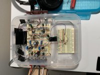
I have attached a picture of a prototype headphone amp [PHA], and its schematic. It is one-of-a kind. The circuit of PHA embodies H2 negative phase [H2np] and classical Positive Current Feedback [PCF]. Thus; in operation:
1. Music fundamental frequencies are first passed through an OpAmp-based Harmonic Generator [HG]. HG imbibes the fundamental frequencies with their second harmonics of negative phase [H2np].
2. The resultant and favorably-modified music signal is then passed to an OpAmp-based low power output amplifier. This amplifier uses its headphone load in a classical [PCF] circuit.
This headphone amp sounds sweet and is highly detailed. I perceived its music outside the confines of my head; which is probably due to [H2np]. The extent of PCF used affected the 'spectral balance" of the parent headphone output; favorable.
I'll have more details in the Class aP amplification thread.
Best
Anton
Attachments
![Headphone Amp [ HA-H2nPCF].png](/community/data/attachments/715/715972-491efb140dff0c479deb2fb6b3a0c355.jpg?hash=SR77FA3_DE)
Things are on schedule, no problems......
I am awaiting 2nd generation prototype boards, these just to catch any artwork error.
Hopefully (pretty please) you might have some surplus boards? I've opted for the measurement workshop. Haven't quite mastered personal cloning in order to attend both. It would be great if I could take home something to build. That would be a great event souvenir.
Many thanks to all concerned. Looking forward to catching up.
I understand that the day after the workshop there will be some available for sale.
Not very many though.
Not very many though.
So, if one decides to take along a diy linestage, like for example a Pass ba-3 linestage, how does one pass it thru TSA security as carry on... with all that wiring, transformers, etc... Or would it have to be checked in? Thanks!
I understand that the day after the workshop there will be some available for sale.
Not very many though.
Thanks for the response.
Good news. I'll take my chances.
Sigh, I’d so attend the workshop this year if I wasn’t getting married in December. My fiancé is tolerant of equipment all over the house and me buying parts when I please but I doubt she’d approve me taking a trip before a honeymoon ha
Bring her along. My wife could have cared less about BA. Last year was the first for me, I went played diy and she enjoyed San Fran.
She’s so pre occupied with wedding planning that I’m 95% sure she wouldn’t go for it plus using the cash on something other than our honeymoon. She use to live in Vacaville and Vallejo and has some friends she wouldn’t mind seeing but it’s bad timing. I’m sure I can swing next year though


Gee....and I was just thinking, 2 inputs with one headphone and one line output.... 🙂
Someone is bound to ask: Does it drive the F4? 😀😀😀
Someone is bound to ask: Does it drive the F4? 😀😀😀
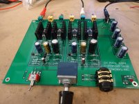
ccs feeds lpt feeds optobiased source follower stage
SMPS wall wart with CRCRCRCRCRCRC RC
Can I find a way to take the time off and travel ...11940kms for the experience? I'd like to dammit!
SMPS wall wart with CRCRCRCRCRCRC RC
naah
you forgot at least one RC

Look more closely, the supply splits into two separate rails after the 2nd RC filter. One rail for the left channel, another rail for the right channel. Then there is a third RC filter on each of these individual rails.
Making a couple wild guesses: Suppose R=0.33 ohms and suppose C is a Kemet "EST" electrolytic, 1000 microfarads, with an ESR of about 50 milliohms, ...
then the "Elmore time constant" (for you VLSI lovers) at the far end of the RC tree, where the active circuits connect to the rail, is 8 * 0.33 * 1000uF = 2.6 milliseconds, very roughly corresponding to a -3dB corner frequency of about 60 Hz. If the SMPS noise to be removed is at 50 kHz, (1000X higher!), the filter will do a great job.
At high frequencies where ESR dominates, each stage will very roughly attenuate by a factor of (0.05 / 0.33) = -16 dB. Since there are three stages in series, the final attenuation will be, very roughly, -48dB.
LTSPICE simulation more or less agrees with these pencil and paper estimates; -3dB at 60 Hz, final attenuation -56dB:
_
Attachments

Last edited:
- Home
- Amplifiers
- Pass Labs
- Burning Amp Festival 2019 with Build and Measurement Workshops!