That is correct. On most fets, not sure about all, the drain pin is electrically connected to exposed metal on the back of the fet. William is right about the D+ voltage. If the bias boards are working, then set it to zero or any number 3V and below. I said 3V because for the IRF, this should be below their turn on voltage. Zero is safer. If you fet are ok, then you now only need to watch the Vdrop across the source resistors of the fets and offset between output and ground. When turning up the bias, a quick way to make sure the fets are sharing current evenly is to check the Vdrop across each fets Rs on the top and bottom. They shoud be close to the same. Check it at a low bias of .050V across the Rs. This is a low enough current that if you have some issues, you still should be safe from cooking other fets.
Looking Good !
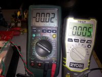
No continuity - both adjusted to ~ 0 DC.
Ready for front end ?
No continuity - both adjusted to ~ 0 DC.
Ready for front end ?
Attachments
Last edited:
yep
Re-check the DC offset after warm-up
Check voltage across source R's as buzz has suggested, could be ugly with a bunch of unmatched devices
Re-check the DC offset after warm-up
Check voltage across source R's as buzz has suggested, could be ugly with a bunch of unmatched devices
Got music !
The problem channel is still softer than the other, but both adjusted to 0 VDC after attaching the front end. I'll let it burn in a little and check back in the morning.
I have learned so much over the past few days and am truly grateful to all.

The problem channel is still softer than the other, but both adjusted to 0 VDC after attaching the front end. I'll let it burn in a little and check back in the morning.
I have learned so much over the past few days and am truly grateful to all.

It's a GOOD feeling after all those problems are gone ,write them down while you got them fresh ,just in case you need them again,
Happy listening!
NS
Happy listening!
NS
anyone ?
I just wound a transformer and it running through a full wave bridge to 66,000 uf caps,
I hooked up the scope with no load and have ripple at 2mv at 6mhz,
Do I need to get rid of it or is that ok?
If it needs attention what is suggested?
Thanks,
NS
I just wound a transformer and it running through a full wave bridge to 66,000 uf caps,
I hooked up the scope with no load and have ripple at 2mv at 6mhz,
Do I need to get rid of it or is that ok?
If it needs attention what is suggested?
Thanks,
NS
you have a good scope , and eyes too , if you can observe mHz

put some bypass caps on final biguns , even if that's certainly filth from environment , not PSU itself
put some bypass caps on final biguns , even if that's certainly filth from environment , not PSU itself
hi zen,
hi Zen,😀
The scopes rated to 150mhz, I payed dearly for it 30 years ago and it still works fine,lol.It was made by KENWOOD and I can make it big enough for a oldman like me to see,lol.
So if I put some small caps on the end of the big uns it should decease ,and yes could be stray caps there,it's not in a chassis yet ......
Thanks,
NS🙂
you have a good scope , and eyes too , if you can observe mHz
put some bypass caps on final biguns , even if that's certainly filth from environment , not PSU itself
hi Zen,😀
The scopes rated to 150mhz, I payed dearly for it 30 years ago and it still works fine,lol.It was made by KENWOOD and I can make it big enough for a oldman like me to see,lol.
So if I put some small caps on the end of the big uns it should decease ,and yes could be stray caps there,it's not in a chassis yet ......
Thanks,
NS🙂

Andrew,
Out of curiosity, on another thread you were talking about segmenting micas into thinner layers -difficult to comprehend based on this experience. How did you install those, and were you using something wider than TO-220?
This morning I swapped the front end leads to confirm the channel volume imbalance is coming from it and not the bias or output boards. What adjustments/readings are needed to get that resolved?
Attachments

Last edited:
use TO3 mica
punch hole where needed (appropriate screw & nut)
screw as patricle and nut as matricle
cut unneeded with scissors
punch hole where needed (appropriate screw & nut)
screw as patricle and nut as matricle
cut unneeded with scissors
I think for most part, interface thing is overdone. If that tiny bit of extra efficiency is needed, time to get bigger sinks. Most any choice done properly, is fine.
Easiest way is scope and dedicated signal. ITs unlikely that it is bias boards if all measurements are comparable there. Take time and go through both channels of bias/output boards. Right down the key voltages on paper and compare. Lets eliminate any possibility there. Sounds more like a FE thing, but no reason not to be thorough. Main points of concern on output boards are Rs vlues of each fet. For kicks, measure the D+ and D- values to see if they are close/similar.
Understood - that will take a while, but I'll put all the readings together on a photo/diagram. Be back soon.....
I don't own a scope, but if I can get an audio interface for my iPad from Staples today - there are a couple apps that might get me in the ballpark. (I needed an excuse to do that 🙄)
I don't own a scope, but if I can get an audio interface for my iPad from Staples today - there are a couple apps that might get me in the ballpark. (I needed an excuse to do that 🙄)
Last edited:
With any set signal, you can take scope or DMM and watch AC output. IT will tell you if the signal is trying to run away and prevent you from having fun.
- Home
- Amplifiers
- Pass Labs
- Burning Amp BA-3