Make sure you measure offset before the output cap. Other than that, it is pretty straightforward. Ask any questions you have. Jfets are good if you have between 6-7ma across jfet Rs.
Is there a published build and/or initial start-up/test/adjustment procedure for the BA-3 front end somewhere on the forum? I haven't located one yet. Would be good to confirm proper operation before I hook it up to something else.🙄
It's essentially an F5 in topology, so treat it like an F5 ---
Turn down the bias pots, neutralize the 2nd harmonic pot.
Get out your three meters just like an F5. Turn up the bias pots equally until there is some voltage across R10 and R11.
Increase bias about 20% at a time, and null your offset at each increase.
Lather, rinse, repeat until you have 1V across the output source resistors and zero offset.
That should be good.
He's Back 🙄
Does anyone have a part number(s) for P1/2 P3 on the BA-3 FE board. I ordered these and received standard vertical three pin trimmers. From the traces, I'm assuming all four leads on those pads are necessary. I spent some time at Mouser but can't put my finger on the exact combination of orientation and pins.
Does anyone have a part number(s) for P1/2 P3 on the BA-3 FE board. I ordered these and received standard vertical three pin trimmers. From the traces, I'm assuming all four leads on those pads are necessary. I spent some time at Mouser but can't put my finger on the exact combination of orientation and pins.
Attachments
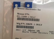
The offset pin and the in-line pin are there for convenience, to fit various types/brands of pots.
The ones you have are great. 🙂
The ones you have are great. 🙂

Yes.
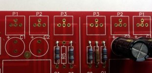
The green T junction away off to the right hand side is your MAG.
The R of the CRC is a little unconventional in that both appear in the +ve side of the cap banks. I think that theoretically they perform just as well as doing one in +ve and one in -ve.
Remember to keep twisted pairs/triplets to as close as the PCBs allow.
Pass DIY Addict
Joined 2000
Paid Member
Hi Guys,
I ordered some 2sk2013 and 2sj313 transistors from Arie on eBay and had the opportunity to measure them (20v and about 45mA) last night. My result as are below:
2sk2013: 2.18, 2.20, 2.20, 2.27, and 2.28
2sj313: 2.04, 2.07, 2.12, 2.15, and 2.16
Are these "close enough" matches that I can use the trim pots for adjustment, or do I need closer matches?
Pass DIY Addict
Joined 2000
Paid Member
Yes, but don't I need to match across the two types for a BA-3 front end? Thus, my best match is 2.16 and 2.18. From there it gets worse: 2.15 and 2.20 followed by 2.12 and 2.20. Are these useful or do I need tighter matches?
Pass DIY Addict
Joined 2000
Paid Member
Sorry Buzz, I feel like I'm being dense here-perhaps I'm missing something. Doesn't each channel of the BA-3 front end have one N and one P channel MOSFET at the output? How does matching N to N and P to P enter into this?
It's not real important, but doing so would make two channels similar to each other. P3 is the great equalizer in the equation within a channel. Euvl has shown J313 and 2013 aren't perfect complimentary pairs and getting them close will take more selection. Run with what you got, if you like the amp, you can push further into performance improvements. This assumes you think they are needed.
Pass DIY Addict
Joined 2000
Paid Member
Guess I'll start populating the boards soon and see where it goes from there... 6L6 provided a nice reference for adjusting distortion while looking at harmonics.
single point matched does not do much for amplifying performance.
It's how well they match when the current sweeps to either side of the set bias current. This is effectively a form of curve matching. An easy way to do that is by 3point matching.
Single point is great for multiple pairs when trying to set bias currents.
It's how well they match when the current sweeps to either side of the set bias current. This is effectively a form of curve matching. An easy way to do that is by 3point matching.
Single point is great for multiple pairs when trying to set bias currents.
Pass DIY Addict
Joined 2000
Paid Member
Andrew, By 3-point matching, do you mean matching each set of transistors at three different currrent levels? In the case of the BA-3, the circuit indicates 45mA, so would I match at say 20mA, 30mA, and 45mA?
Hmmm... I don't even really have a match at 45mA here. I suppose I'll build the circuit and see what I get with the tools that 6L6 pointed out. This will take me a little while - too many other things going on right now. All of my projects seem to be on extended timelines.
Hmmm... I don't even really have a match at 45mA here. I suppose I'll build the circuit and see what I get with the tools that 6L6 pointed out. This will take me a little while - too many other things going on right now. All of my projects seem to be on extended timelines.
- Home
- Amplifiers
- Pass Labs
- Burning Amp BA-3