I changes 6k to 1,15 and it worked differently. Sören said he tested with 1k. My build is so hard to access so I didn't want to take another chance 🙂
//
//
Hi Soekris
to connect the SPDIF inputs
FPGA LVDS Receiver need to be biased around 1.25V the same dam1021?
Thanks
to connect the SPDIF inputs
FPGA LVDS Receiver need to be biased around 1.25V the same dam1021?
Thanks
Hi Soekris,
I connected DAM1121 such as:
Computer to FT232RL 3.3V 5.5V FTDI USB to TTL Serial Adapter Module for Arduino Mini Port | eBay to Dam1121. But it cans not work. Whats wrong?
I connected DAM1121 such as:
Computer to FT232RL 3.3V 5.5V FTDI USB to TTL Serial Adapter Module for Arduino Mini Port | eBay to Dam1121. But it cans not work. Whats wrong?
Hi Soekris
to connect the SPDIF inputs
FPGA LVDS Receiver need to be biased around 1.25V the same dam1021?
Thanks
No, please se dam1121 manual for details and example schematics.
Hi Soekris,
I connected DAM1121 such as:
Computer to FT232RL 3.3V 5.5V FTDI USB to TTL Serial Adapter Module for Arduino Mini Port | eBay to Dam1121. But it cans not work. Whats wrong
Have no clue, you haven't provided details.... The dam1121 serial port works, I use it for testing and programming. Again, see manual for details.
Second model DAM, second set of speakers gone. Started left up - played OK. Started right, got uM connection. R goes bananas at full pelt - no command given. But then, without touching L, L also goes full pelt. Smoke. I will now go sailing 🙂
MacBook -> CoolTerm -> Bluetooth -> BT type1 -> DAM -> NC400 / SMPS600 -> speaker.
The other channel uses BT Type2.
The terminal on Left was empty - no readings/changed state - still it went full volume with result as per picture.
R was in uManager looking like this at the time of the incident:
# set
Conspeed = 9600
Volume = -25
Filter = Linear
Mode = Bal-Right
#
//
Well, I think I should update on this. It is now obvious that I had not strapped the DAM in a correct way. So for the record - this was most probably my fault.
//
Well, I think I should update on this. It is now obvious that I had not strapped the DAM in a correct way. So for the record - this was most probably my fault.
//
Seriously can't you test with a set of headphones and a headphone amp? Or a considerably less powerful amplifier?
1.I'd like to know what diffrent between J2 PIN1 and J2 PIN2.(VCC5D&VPWR)
2.Is it necessary to separate two LDO to power supply?
3. if I use two LDO to supply,and when I need pullup other pin for set 1121 mode,witch one should I to connect?
2.Is it necessary to separate two LDO to power supply?
3. if I use two LDO to supply,and when I need pullup other pin for set 1121 mode,witch one should I to connect?
Last edited:
1.I'd like to know what diffrent between J2 PIN1 and J2 PIN2.(VCC5D&VPWR)
2.Is it necessary to separate two LDO to power supply?
3. if I use two LDO to supply,and when I need pullup other pin for set 1121 mode,witch one should I to connect?
The dam1121 Manual says both are VCC5D, so they both need to be connected to same 5V source.
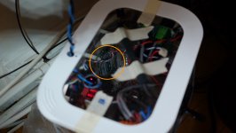
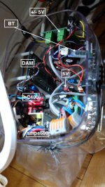
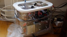
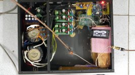
Presenting my use of the DAM 1121. I choose it because for two major reasons. Size and the re-clocking after the FPGA.
Each box (2) is composed by:
# 1 DAM-1121
# 3x Meanwell RS-15-15
# 1,5 (one bord split in half) Diyinhk LT3042 based 0.8uV Ultralow noise DAC power supply regulator 3.3/5/7V 1.5A*x2 (DAM needs 3x 5volt supplies). I cut/saw one in half.
# 1 TPS7A47 based 3,3 volt regulator board for Toslink receiver.
# 1 Wireless Serial 4 Pin Bluetooth RF Transceiver Module RS23 HC-06 with backplane (ebay)
# 1 Toslink receiver - Toshiba TORX147L TORX147 15Mbps Fiber Optical Receiver 3 pin x 1PC (ebay)
# 5 meter Toslink cable
# Active Toslink splitter - White SPDIF TOSLINK Digital Optical Audio 1 x 3 Splitter (1 Input 3 Outputs) New (ebay)
# 1 Hypex nC400
# 1 Hypex SMPS600
I feed these from a Squeezbox Touch via the toslink splitter using the SB volume control. DAM gain is set to -14 this s till gives enough level.
Plastic box, nylon standoffs and div cables etc.
Design requirements:
- Absolutely shortest analog path length
- No life sucking metal housing
Result: SQ is superior to all other combination I have had previously (don't they all 🙂 ) Particularly dynamics is excellent. It scare you sometimes which is a good sign. Very good hight and space but still focused. Musical 🙂
Recommended.
//
Attachments
Last edited:
Nice job, TNT 👊
Agree on not using metal housing - although I have had one perspex-clad 1021 suffer from occasional dropouts. A little square of foil in the right place on the inside of the top cover solved it.
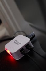
Can you post an eBay link to that Bluetooth unit, please?
Agree on not using metal housing - although I have had one perspex-clad 1021 suffer from occasional dropouts. A little square of foil in the right place on the inside of the top cover solved it.
Can you post an eBay link to that Bluetooth unit, please?
Thanks!
I belive it was this: Wireless Serial 4 Pin Bluetooth RF Transceiver Module HC-06 RS232 With backplane | eBay
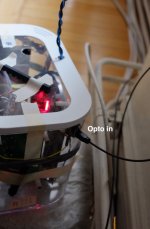
There is also a switch on the front. It cuts the 3,3v to the BT so to avoid BT RF chitter-chatter.
My DAMs of course drive the nCores differentially.
//
I belive it was this: Wireless Serial 4 Pin Bluetooth RF Transceiver Module HC-06 RS232 With backplane | eBay
There is also a switch on the front. It cuts the 3,3v to the BT so to avoid BT RF chitter-chatter.
My DAMs of course drive the nCores differentially.
//
Sören,
Using two DAM1121 with SI570, one sets in the master and send clk+- to slave, do I need to put max9180 reapter between both board?? okay to connect directly?
Wonder it is better to use one si570 on the base board and not use si570 on board like example. In this case, I must use max9180? or okay to just split clk+- signal direcly to two dam1121 boards?
Sören,
Using two DAM1121 with SI570, one sets in the master and send clk+- to slave, do I need to put max9180 reapter between both board?? okay to connect directly?
Wonder it is better to use one si570 on the base board and not use si570 on board like example. In this case, I must use max9180? or okay to just split clk+- signal direcly to two dam1121 boards?
The dam1121 clocks are LVDS signals and should be routed and terminated correctly, with only very short stubs.
So when using one boards oscillator as master it should be buffered with a LVDS buffer, like a max9180, otherwise you will have two signal routes driving by one oscillator, meaning incorrectly double terminated.
When using an external Si570 oscillator driving two boards you will also need a LVDS buffer, otherwise it's the same result as above. If the oscillator is not directly close to one of the boards, you will need a two output LVDS buffer, one to drive each board.
When using an external Si570 oscillator driving more than two boards you will also need a multi output LVDS buffer.
Thanks, Sören.
In my case, both dam1121 have si570 on board, so can I just set both in master mode and split i2s and spdif signal to each board?
In the manual, if I set board to master, I2S_OUT is active. Can I still use CFG3~1?
In my case, both dam1121 have si570 on board, so can I just set both in master mode and split i2s and spdif signal to each board?
In the manual, if I set board to master, I2S_OUT is active. Can I still use CFG3~1?
Thanks, Sören.
In my case, both dam1121 have si570 on board, so can I just set both in master mode and split i2s and spdif signal to each board?
In the manual, if I set board to master, I2S_OUT is active. Can I still use CFG3~1?
Yes, you can also run the dam1121 in async mode, setting both boards as master and connecting same input signals to both. I2S_OUT will be outputs, but they will of course not be connected. CFG3..0 always need to be connected to set mode, but they are sampled only at power up.
Yes, you can also run the dam1121 in async mode, setting both boards as master and connecting same input signals to both. I2S_OUT will be outputs, but they will of course not be connected. CFG3..0 always need to be connected to set mode, but they are sampled only at power up.
just make sure. CFG3..0 only sampled at power up. Is this mean I need some kind of relay control? when its powering up, relay and CFG pins connect to pullup resistor for something like 100ns? after than live these pins open if I am not using I2S_OUT?
Last edited:
just make sure. CFG3..0 only sampled at power up. Is this mean I need some kind of relay control? when its powering up, relay and CFG pins connect to pullup resistor for something like 100ns? after than live these pins open if I am not using I2S_OUT?
No need to do anything fancy, just connect as described in manual and shown in example schematics.
The FPGA set the config pins as inputs during power up, samples the value and then switches to outputs. The config pullup/pulldown resistors can be connected permanently.
Last edited:
- Home
- Source & Line
- Digital Line Level
- Building with the Soekris dam1121