Hi maxlorenz,
No, Yes, the part is already on it's way.
Silicon glue could contain acid, this could cause the pins to corrode. You could use kit that contains no acids. It's also possible to use the insulation from equipment wire, cut small 2mm pieces of it, and slide it over each TDA1543 pin. You could also try placing a thin sheet of insulation material between heatsink and TDA1543 pins, then fixate it with glue.
I asume you were talking about the current sources...I thought you were talking about my project...
No, Yes, the part is already on it's way.
How about using silicone glue between IC pins and heatsinks? Will this degrade sound?
Silicon glue could contain acid, this could cause the pins to corrode. You could use kit that contains no acids. It's also possible to use the insulation from equipment wire, cut small 2mm pieces of it, and slide it over each TDA1543 pin. You could also try placing a thin sheet of insulation material between heatsink and TDA1543 pins, then fixate it with glue.
Re: SPDIF > (D)I2S schematics
Thanks a lot -ecdesigns-, as always your replay is very detailed and usefull, really kind.
ciao
andrea
Thanks a lot -ecdesigns-, as always your replay is very detailed and usefull, really kind.
ciao
andrea
Hi tubee,
The PCB is only a prototype. If sufficient people are interested in building these modules (it can also be used to drive other NOS DACs), I could have some professional PCBs and CS8414 adapter boards manufactured.
The SMD crystal oscillator module is from CTX, I sourced it from Digikey, P/N CTX315LVCT-ND.
Datasheet:
http://rocky.digikey.com/scripts/ProductInfo.dll?Site=US&V=110&M=CB3LV-3I-48M0000
Phase jitter (tjms) is specified at <1ps RMS (bandwidth 12 KHz...20 MHz)
Thanks for reply John. Good news the spdif finally sound as good as from pc. I have a CS8414 unused here so can build a dac input from it. Do you have a pcb available? And which make xtal is used?
The PCB is only a prototype. If sufficient people are interested in building these modules (it can also be used to drive other NOS DACs), I could have some professional PCBs and CS8414 adapter boards manufactured.
The SMD crystal oscillator module is from CTX, I sourced it from Digikey, P/N CTX315LVCT-ND.
Datasheet:
http://rocky.digikey.com/scripts/ProductInfo.dll?Site=US&V=110&M=CB3LV-3I-48M0000
Phase jitter (tjms) is specified at <1ps RMS (bandwidth 12 KHz...20 MHz)
-ecdesigns- said:SCK (BCK) pin12 enters the shiftregister reclocker first (U2, U3, U4). The shiftregister reclocker is clocked by a very low jitter (<1ps) 48 MHz master clock (U5).
I hope everyone realizes that the inherent jitter of the reclocking oscillator has very little effect on the sample clock jitter as seen by the DAC chips. To understand the fallacy of reclocking as a way to reduce jitter, let’s analyze a basic reclocking circuit. For this discussion, let’s also assume that SCLK and the reclocking oscillator (RCLK) have zero jitter and the logic gates are infinitely fast with zero propagation, setup, and hold times.
At time 0, the initial conditions are that SCLK and RCLK change from 0 to 1 simultaneously. Thereafter, SCLK oscillates at 64x44.1KHz, and RCLK oscillates at 48MHz. The DAC chip expects a new sample every 64 SCLK periods.
The 64th rising edge of the ideal, jitter-free SCLK comes at time 22.6757us but the signal does not propagate to the DAC until the next RCLK, which comes at time 22.6875us. As seen by the DAC, the sample clock is 11.763ns late, compared to where it should be for perfect 44.1KHz D-to-A conversion, and the just-ending sample period is stretched to 22.6875us.
The 128th rising edge of the ideal, jitter-free SCLK edge comes at time 45.3515us and it doesn’t propagate to the DAC chip until the next RCLK, which comes at time 45.3542us. As seen by the DAC, the sample clock is 2.693ns late, compared to where it should be for perfect 44.1KHz D-to-A conversion, but this time the just-ending sample period is shortened to 22.6667us.
The first few clock periods can be summarized as follows:
Code:
sample time   reclock time  sample jitter   sample period   implied sample
ideal (us)    actual (us)   actual (ns)     actual (us)     rate (KHz)
  0.0000        0.0000         -               -              -
 22.6757       22.6875      11.7630         22.6875         44.08
 45.3515       45.3542       2.6927         22.6667         44.12
 68.0272       68.0417      14.4558         22.6875         44.08
 90.7029       90.7038       5.3855         22.6667         44.12
113.3787      113.3958      17.1485         22.6875         44.08
136.0544      136.0625       8.0782         22.6667         44.12
158.7302      158.7500      19.8413         22.6875         44.08
181.4059      181.4167      10.7710         22.6667         44.12
204.0816      204.0833       1.7007         22.6667         44.12
226.7574      226.7708      13.4637         22.6875         44.08
Continuing the above table for many thousands of sample periods, we find the peak-to-peak jitter is 20.8333ns, which is the period of the 48MHz reclock oscillator, and the rms jitter is 12.0264ns. Adding 200ps of SCLK jitter and 1ps of RCLK jitter to the above calculations only increases the rms sample clock jitter by a very small amount.
Asynchronous reclocking extends every sample period to an integral number of reclock periods thereby adding jitter equal to the period of the reclock oscillator.
It is easy to see 12ns jitter with a ‘scope. All you need is a trigger that is synchronous with the true, 44.1KHz sample clock. For that you can use a semi-pro sound card that has S/PDIF and word clock outputs, such as Lynx or RME. Trigger the ‘scope with word clock and look at the CS8412 signals FSYNC, SCLK and the output of the reclock circuit, BCLK.
FSYNC will have essentially no jitter because the CS8412 generates FSYNC from the timing of the bi-phase preambles, which are timed by the word clock of the transmitter. FSYNC is the next best thing to an external word clock. SCLK will have about 200ps rms jitter, which is the spec of the CS8412’s PLL and may not be visible. BCLK will have at least 12ns rms jitter and will be very visable.
-ecdesigns-: The clock choice is up to you. You may prefer the sound of a high-jitter sample clock, many audiophiles do, but don’t misrepresent your DACs as having low sample-clock jitter. On you web site your say:
The USB interface has a unique shiftregister reclocker that provides extreme low jitter, regardless of digital audio source jitter.
To be honest, what you should say is:
The USB interface has a unique shiftregister reclocker that provides high jitter, regardless of digital audio source jitter.
Hi Whatsup:
If you compare a signal with a 44.1 khz signal from a soundcard, how do you know if that particular soundcard is not jittery itself?
If you compare a signal with a 44.1 khz signal from a soundcard, how do you know if that particular soundcard is not jittery itself?
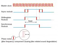
The jitter frequency component that causes sound quality degradation
Whatsup Hi,
Are you sure about this? somehow I get doubts about this statement. What about digital audio source (CD transport) timing jitter? the relatively long SPDIF interlink and the resulting interference between data and sync components in the SPDIF signal? CS8412 on-chip crosstalk between DATA and WS / BCK?
You are absolutely correct about the phase deviations introduced by asynchronous reclocking. Sure I noticed these phase deviations during measurements, they are clearly visible (illustrated by oscillograms I posted earlier on this thread)
But tests I conducted showed that the low amplitude phase noise causes most problems. This was verified by both measurements and listening tests. It turns out that these very small phase deviations disrupt feedback loops in analog stages (DAC, pre-amplifier, power amplifier). Simple comparison tests between two power amps of the same type, one with high negative feedback, the other with significant lower feedback showed that the one with highest feedback produced sound degradation very similar to increased phase noise.
So I think that the jitter related sound degradation is primarily caused by disruption of analog circuits / feedback loops , rather than changing absolute sample timing.
I added a drawing for explanation:
The master clock is on top, the red colour indicates phase noise, random jitter in the (almost zero) to say 1000ps range, depending on master clock oscillator jitter.
First is the signal produced by an asynchronous reclocker, causing the phase deviations you correctly described. Note that clock signal phase only "jumps" between fixed points rather than fluctuating randomly.
Superimposed on these fixed phase deviations (determined by master clock positive clock transition), is the actual phase noise, also present on the master clock (marked red). It's very likely this phase noise is further amplified by imperfections in the reclock circuit.
Next is the shiftregister reclocker (basically a digital one-shot circuit), due to the forced reset, the majority of master clock transients are detected without causing a phase deviation. This results in sporadic phase fluctuations (thin green coloured pulse). This comes very close to the ideal, a synchronously reclocked signal, indicated at the bottom.
But all clock signals, no matter how they are generated, still contain the master clock phase noise and therefore will degrade sound quality. I magnified this part to illustrate this is random phase noise.
So in my opinion, the most important is very low master clock jitter. Digital audio interface receivers based on PLL circuits do produce quite a lot of phase noise, on all signals (including framesync), values between approx. 250 and 1000 ps are quite common in practical circuits with practical interface cable lengths. Reclockers can significantly reduce this phase noise.
Then there is the very tricky (on-chip) crosstalk between DATA and timing signals, making it quite problematic to obtain both DATA and low jitter timing signals from one chip.
The synchronous reclocker is theoretically best, but often difficult to realize. The shiftregister reclocker will lock on high jitter signals, synchronize the output clock transients with the master clock, adding mainly the master clock phase noise, independent of the digital sound source phase noise. It's a simple circuit, not expensive, why not use it.
I will rephrase the remark I made for clarity:
The USB interface has a unique shiftregister reclocker that provides extreme low phase noise (frequency components that result in sound quality degradation), regardless of digital audio source jitter.
Whatsup Hi,
FSYNC will have essentially no jitter because the CS8412 generates FSYNC from the timing of the bi-phase preambles
Are you sure about this? somehow I get doubts about this statement. What about digital audio source (CD transport) timing jitter? the relatively long SPDIF interlink and the resulting interference between data and sync components in the SPDIF signal? CS8412 on-chip crosstalk between DATA and WS / BCK?
You are absolutely correct about the phase deviations introduced by asynchronous reclocking. Sure I noticed these phase deviations during measurements, they are clearly visible (illustrated by oscillograms I posted earlier on this thread)
But tests I conducted showed that the low amplitude phase noise causes most problems. This was verified by both measurements and listening tests. It turns out that these very small phase deviations disrupt feedback loops in analog stages (DAC, pre-amplifier, power amplifier). Simple comparison tests between two power amps of the same type, one with high negative feedback, the other with significant lower feedback showed that the one with highest feedback produced sound degradation very similar to increased phase noise.
So I think that the jitter related sound degradation is primarily caused by disruption of analog circuits / feedback loops , rather than changing absolute sample timing.
I added a drawing for explanation:
The master clock is on top, the red colour indicates phase noise, random jitter in the (almost zero) to say 1000ps range, depending on master clock oscillator jitter.
First is the signal produced by an asynchronous reclocker, causing the phase deviations you correctly described. Note that clock signal phase only "jumps" between fixed points rather than fluctuating randomly.
Superimposed on these fixed phase deviations (determined by master clock positive clock transition), is the actual phase noise, also present on the master clock (marked red). It's very likely this phase noise is further amplified by imperfections in the reclock circuit.
Next is the shiftregister reclocker (basically a digital one-shot circuit), due to the forced reset, the majority of master clock transients are detected without causing a phase deviation. This results in sporadic phase fluctuations (thin green coloured pulse). This comes very close to the ideal, a synchronously reclocked signal, indicated at the bottom.
But all clock signals, no matter how they are generated, still contain the master clock phase noise and therefore will degrade sound quality. I magnified this part to illustrate this is random phase noise.
So in my opinion, the most important is very low master clock jitter. Digital audio interface receivers based on PLL circuits do produce quite a lot of phase noise, on all signals (including framesync), values between approx. 250 and 1000 ps are quite common in practical circuits with practical interface cable lengths. Reclockers can significantly reduce this phase noise.
Then there is the very tricky (on-chip) crosstalk between DATA and timing signals, making it quite problematic to obtain both DATA and low jitter timing signals from one chip.
The synchronous reclocker is theoretically best, but often difficult to realize. The shiftregister reclocker will lock on high jitter signals, synchronize the output clock transients with the master clock, adding mainly the master clock phase noise, independent of the digital sound source phase noise. It's a simple circuit, not expensive, why not use it.
I will rephrase the remark I made for clarity:
The USB interface has a unique shiftregister reclocker that provides extreme low phase noise (frequency components that result in sound quality degradation), regardless of digital audio source jitter.
Attachments
DAC habemus
Finally, after a little problem I have my DI8*4 DAC making music 😎
I hate to sound as reckless and bold as -ecdesigns- but this new DAC really has significant resolution enhancement over DI16, really HiEnd stuff.
I don't know how much is due to the USB/DI2S module and how much due to the paralelling of the DAC's...
Think of a modern 24bit OS-DAC but with the humanity of NOS-DACs.
Everything improved: HF extension, detail and sweetness; rithm and pace; instruments separation...etc.
It sounds cleaner also, with more articulation on instrumental lines.
I bet it sounds better than your DI8M
You were right again and I will have to install a plate over the towers bolted to chassis to get rid of the heat. Around 55° says my finger...
I will have to transform my DI16...next year maybe...
Thanks for your help and obviously for your (our) invention. 😀
M
The copper foil mod
Hi maxlorenz,
If I am correct habemus is Latin for "we have", so DAC habemus (we have a DAC)
Good to hear your DI 16 (8*4) is working.
Based on the tests I performed, the shiftregister reclocker would have made the biggest improvement, the 8*4 mod is a bit more subtle (faster response and more detail).
My brother recently compared the plain DI 16 with his NOS twin DAC (2 * TDA1541A with 8th order Butterworth filter using LM4562 in class A, and a USBDI2S module). The DI 16 outperformed it (faster, more detail), so it seems very good results can be achieved with the TDA1543.
The DI 8M is very hard to beat, I leave it at that 😎
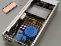
There is a new mod, It was a result of trying to reduce electromagnetic interference. I used self-adhesive copper foil for screening the ICs. I wrapped it around all ICs, and put small pieces on top of SMD ICs. The sheets are not grounded. The idea is to turn HF energy into Eddy currents (copper foil), converting part of it into heat.
Well it seems to work quite well, the DI DACs are now less sensitive to external EMC sources like HF tube-lighting, WLAN, DECT and GSM for example (these could cause increase of jitter). Also chip to chip crosstalk has been reduced. Power supply decoupling seems to reach its limits at some point, as the electromagnetic interference from the ICs directly affects the components located close to it.
The timing signal transients look slightly cleaner on the oscilloscope now. The sound is slightly more "analogue", clearer, and very relaxing.
The self-adhesive copper tape isn't expensive, so it's worth a try. The only "problem" is that it will take some time and patience to perform this mod.
I added a photograph to illustrate this mod. The foil is wrapped around the chip (bottom, one side and top of the chip). The copper foil tape must be firmly pressed against the chip surface in order to guarantee good fixation. I used copper foil strips of approx. 5.5mm (0.2") wide, care should be taken to avoid short circuit with the IC pins.
I used some car wax to prevent oxidation of the copper foil, another option is to use tinned copper foil.
Hi maxlorenz,
If I am correct habemus is Latin for "we have", so DAC habemus (we have a DAC)
Finally, after a little problem I have my DI8*4 DAC making music 😎
Good to hear your DI 16 (8*4) is working.
Based on the tests I performed, the shiftregister reclocker would have made the biggest improvement, the 8*4 mod is a bit more subtle (faster response and more detail).
My brother recently compared the plain DI 16 with his NOS twin DAC (2 * TDA1541A with 8th order Butterworth filter using LM4562 in class A, and a USBDI2S module). The DI 16 outperformed it (faster, more detail), so it seems very good results can be achieved with the TDA1543.
I bet it sounds better than your DI8M
The DI 8M is very hard to beat, I leave it at that 😎
There is a new mod, It was a result of trying to reduce electromagnetic interference. I used self-adhesive copper foil for screening the ICs. I wrapped it around all ICs, and put small pieces on top of SMD ICs. The sheets are not grounded. The idea is to turn HF energy into Eddy currents (copper foil), converting part of it into heat.
Well it seems to work quite well, the DI DACs are now less sensitive to external EMC sources like HF tube-lighting, WLAN, DECT and GSM for example (these could cause increase of jitter). Also chip to chip crosstalk has been reduced. Power supply decoupling seems to reach its limits at some point, as the electromagnetic interference from the ICs directly affects the components located close to it.
The timing signal transients look slightly cleaner on the oscilloscope now. The sound is slightly more "analogue", clearer, and very relaxing.
The self-adhesive copper tape isn't expensive, so it's worth a try. The only "problem" is that it will take some time and patience to perform this mod.
I added a photograph to illustrate this mod. The foil is wrapped around the chip (bottom, one side and top of the chip). The copper foil tape must be firmly pressed against the chip surface in order to guarantee good fixation. I used copper foil strips of approx. 5.5mm (0.2") wide, care should be taken to avoid short circuit with the IC pins.
I used some car wax to prevent oxidation of the copper foil, another option is to use tinned copper foil.
Attachments
Hi John,
I am interested by your copper foil mod.
Are the thickness and dimensions of the copper important do you think? Would a ferrite tape be more effective ? Something like this perhaps http://kerafol.de/jml/pdfdocs/ferrit/f96_e.pdf. What about wrapping the IC in copper tape (connected to the ground plane) and then ferrite tape over the top ? I wonder if you have compared your mod with and without grounding the foil ?
Cheers,
Jon
Shielding of chips with copper foil helps and is easy to do.
Unfortunately here in Holland it swerms of hf around here nowadays: Dect of neighbours, GSM, UMTS, wifi of neighbours. It should be prohibited that i suffer from someone else's HF radiation. I don't want all that radiation, but cannot do anything about it. I am sure it is not healthy either.
Unfortunately here in Holland it swerms of hf around here nowadays: Dect of neighbours, GSM, UMTS, wifi of neighbours. It should be prohibited that i suffer from someone else's HF radiation. I don't want all that radiation, but cannot do anything about it. I am sure it is not healthy either.
I use 3M addresive copper foil - EMI shielding tape.
http://products3.3m.com/catalog/us/...trical_3_0/command_AbcPageHandler/output_html
It works very well. Sound became even better, more natural.
I tried only on all ICs on USB module of DI16 DAC.
I didnt grounding foil, because it seems makes more problems.
regards, Bostjan
http://products3.3m.com/catalog/us/...trical_3_0/command_AbcPageHandler/output_html
It works very well. Sound became even better, more natural.
I tried only on all ICs on USB module of DI16 DAC.
I didnt grounding foil, because it seems makes more problems.
regards, Bostjan
Hi guys,
Hey John, dress all your electrolytics with copper foil and then tell me if you hear something different 😉
The highs of my DI8*4 are superb, very detailed but "human", sweet, vibrating.
😎
Bye,
M
Hey John, dress all your electrolytics with copper foil and then tell me if you hear something different 😉
The highs of my DI8*4 are superb, very detailed but "human", sweet, vibrating.
😎
Bye,
M
maxlorenz said:Hi guys,
Hey John, dress all your electrolytics with copper foil and then tell me if you hear something different 😉
And the next step ?
An externally hosted image should be here but it was not working when we last tested it.
Hi Rfbrw,
That surelly will change your perception of soundstage, but I don't recommend it. You can try it if you want. But don't prolong the foil until it covers your ears
Cheers,
M
That surelly will change your perception of soundstage, but I don't recommend it. You can try it if you want. But don't prolong the foil until it covers your ears
Cheers,
M
maxlorenz said:
You can try it if you want. But don't prolong the foil until it covers your ears
Funny you should say that. I would have thought drop down flaps were de rigeur for filtering out the satanic messages associated with the TDA154*.
An externally hosted image should be here but it was not working when we last tested it.
Hi maxlorenz,
Pioneer did this a long while back. It looked shiny and I guess that was the point.
Did you know they didn't even ground the foil tape? It's about as useful as chrome to make your car go faster.
-Chris
Pioneer did this a long while back. It looked shiny and I guess that was the point.
Did you know they didn't even ground the foil tape? It's about as useful as chrome to make your car go faster.
-Chris
Hi guys,
As you may know, the only Hi-Tech measuring instruments that I own reside inside my skull. When I see an easy to perform test I go for it-> if I like it, it stays...not very objective, I agree, but, I always listen to music in a subjective fashion anyway so I don't see any theoretical problem with that.
I see performing a simple test may not be a la hauteur (sorry, I don't have that accent) of certain scientists...fair enough.
Regards
M
PS: why don't we re-baptize this forum TIYaudio (Talk It Yourself) as so few people actually do something?
maxlorenz said:
PS: why don't we re-baptize this forum TIYaudio (Talk It Yourself) as so few people actually do something?
And then only when you stick a ring through their noses.
a333bt said:I use 3M addresive copper foil - EMI shielding tape.
http://products3.3m.com/catalog/us/...trical_3_0/command_AbcPageHandler/output_html
It works very well. Sound became even better, more natural.
I tried only on all ICs on USB module of DI16 DAC.
I didnt grounding foil, because it seems makes more problems.
regards, Bostjan
If you don't ground the foil you are making the situation worse than no foil at all....

- Home
- Source & Line
- Digital Line Level
- Building the ultimate NOS DAC using TDA1541A