Alexandre - balancing electronic circuits is *the* scientific approach - at least to improve measurements 😉
It´s my experience.
If you find yourself enjoying music more and more with it, then it´s the way to go.
Did you read this piece by mastering engineer Bob Katz? In retrospect, I think the cancellation of second harmonic hurt my musical reproduction. As I said it was refreshing to revert to single DACs.
Katz's Corner Episode 25: Adventures in Distortion | InnerFidelity
In retrospect, I think the cancellation of second harmonic hurt my musical reproduction.
Weissi, just to be clear, I mean a DAC with an odd harmonic character (dominant 3rd) is not as pleasant to me.
Altough vinyl rips sounded great regardless of DAC (these have plenty of H2)!
(Of course, even harmonics that are present in the music are not cancelled - I have seen some people confuse this, I am not one of them).
Thanks,
Alex
Last edited:
We do not need to discuss distortion preferences. I for myself enjoy multibit DACs more than measurement-wise superiour DS DACs. Going balanced is more like a best practice, imroving the current flows in the IC itself. I am far away from understanding if that only affects K2.
Going balanced is more like a best practice, imroving the current flows in the IC itself. I am far away from understanding if that only affects K2.
Weissi, there are pros and cons to most everything.
TDA1543 and 1541 are both capable of constant current operation without resorting to the differential scheme.
For the 1543, disable the internal bias current by leaving pin 7 open (big improvement in sound). Now you have a sink current, zero to 2.3mA. This current must be routed entirely to V+ in order to achieve constant current.
Inside the chip a complementary current flows, Philips papers call it "Idump". Iout+Idump=2.3mA (constant). Measured by me.
This and other refinements (over the years) have produced a tda1543 dac that sounds superb! Dark but airy, detailed, very refined, very extended lows and highs. It is a pleasure to listen to and there is no fatigue. I operate it at 88.2KHz and it is definitely better than NOS.
Thanks,
Alex
Hi Zoran,
thank you for the information!
Greetings,
Xaled
Hi I found philips I2S bus file. please take a look at the additional lines as WSP, WSD...
Attachments
WSD, WSP signals
Hi Zoran,
WSD = WS Delayed, in the document WS is delayed by 0.5 bit. I require a similar timing signal in my converter for sampling the MSBs on the moment these are valid in the centre of the bit.
WSP = WS Pulse, a short pulse (0.5 bit wide) is generated on both transients of the WS signal with an exclusive OR gate (WSD0.5 -XOR- WSD1) to latch registers.
So these are signals derived from WS that are used for driving (on-chip) registers.
Hi Zoran,
Hi I found philips I2S bus file. please take a look at the additional lines as WSP, WSD...
WSD = WS Delayed, in the document WS is delayed by 0.5 bit. I require a similar timing signal in my converter for sampling the MSBs on the moment these are valid in the centre of the bit.
WSP = WS Pulse, a short pulse (0.5 bit wide) is generated on both transients of the WS signal with an exclusive OR gate (WSD0.5 -XOR- WSD1) to latch registers.
So these are signals derived from WS that are used for driving (on-chip) registers.
TDA1540 low frequency DEM
Hi Zoran,
Yes this should be possible as the TDA1540 uses similar DEM circuit as the TDA1541A. Minus goes to the chip decoupling pins, plus goes to GND as with the TDA1541A.
You also need to increase the timing cap value from 820pF to approx. 1uF (between pins 8 and 9). 12K bias resistor may be required too, however I can't check this as I have no TDA1540 chips here.
Hi Zoran,
EC can 100uF/25V value be applied for the TDA1540 14bit dac?
Yes this should be possible as the TDA1540 uses similar DEM circuit as the TDA1541A. Minus goes to the chip decoupling pins, plus goes to GND as with the TDA1541A.
You also need to increase the timing cap value from 820pF to approx. 1uF (between pins 8 and 9). 12K bias resistor may be required too, however I can't check this as I have no TDA1540 chips here.
Hi weissi,
Symmetrical circuits cancel even order harmonics distortion (good sounding to our auditory system).
What remains is dominating odd order harmonics distortion (even very low levels of these are not appreciated by our auditory system).
In other words, 0.01% odd order harmonics distortion can sound much more objectionable than 2% even order harmonics distortion.
Dominating even order harmonics distortion also masks odd order harmonics distortion and this is a good thing when perceived sound quality is most important.
Logical conclusion would be designing circuits with such low THD that dominating odd order harmonics will drop below audibility threshold.
This is very difficult but can be done. However, this approach introduces new audible problems like time smearing for example that may be worse than the problem being addressed.
We do not need to discuss distortion preferences. I for myself enjoy multibit DACs more than measurement-wise superiour DS DACs. Going balanced is more like a best practice, imroving the current flows in the IC itself. I am far away from understanding if that only affects K2.
Symmetrical circuits cancel even order harmonics distortion (good sounding to our auditory system).
What remains is dominating odd order harmonics distortion (even very low levels of these are not appreciated by our auditory system).
In other words, 0.01% odd order harmonics distortion can sound much more objectionable than 2% even order harmonics distortion.
Dominating even order harmonics distortion also masks odd order harmonics distortion and this is a good thing when perceived sound quality is most important.
Logical conclusion would be designing circuits with such low THD that dominating odd order harmonics will drop below audibility threshold.
This is very difficult but can be done. However, this approach introduces new audible problems like time smearing for example that may be worse than the problem being addressed.
BCK sine wave clock.
Hi glowing vinyl,
I assume the idea is generating a very clean, low jitter clock signal for TDA1541A sample timing.
TDA1541A on-chip switching noise (I2S mode) would make it impossible to extract a low jitter sample timing signal from WS and BCK with or without a clean external clock.
I suggest to use it in simultaneous mode with the dedicated LE signal for sample timing. You would then need a 44.1 KHz crystal that has to be synced with the incoming digital audio data signals.
Clock signals with slower transients like sine wave clocks promote trigger uncertainty and jitter in a noisy environment. So a suitable squarer circuit would have to be placed close to the crystal oscillator.
There are several clocking schemes:
- Generate the timing signal directly with a dedicated oscillator that has the correct sample timing frequency.
- Divide a clock signal that is a multiple of the timing signal.
- Synchronous reclocking (works with different sample rates).
Yes of course I did, I follow John Broskie's thread regularly:
Single-Ended Designs
Digital electrostatic speakers are not as simple as it seems, the required ultra high speed HV bit drivers are very difficult to construct. One also has to develop a trace pattern where all bits offer an evenly spread force on the diaphragm in order to prevent unwanted diaphragm resonances.
Hi glowing vinyl,
An idea I've had for a long time but not got round to, is to try clocking the TDA with a SINE wave clock for BCK.
NOS - requires custom XTAL at 2.8...MHz but probably best solution at the end
2) 4 x OS - uses 11.286...MHz XTAL but possible degradation due to OS. I was thinking this is relatively interesting as a proof of concept
I assume the idea is generating a very clean, low jitter clock signal for TDA1541A sample timing.
TDA1541A on-chip switching noise (I2S mode) would make it impossible to extract a low jitter sample timing signal from WS and BCK with or without a clean external clock.
I suggest to use it in simultaneous mode with the dedicated LE signal for sample timing. You would then need a 44.1 KHz crystal that has to be synced with the incoming digital audio data signals.
Clock signals with slower transients like sine wave clocks promote trigger uncertainty and jitter in a noisy environment. So a suitable squarer circuit would have to be placed close to the crystal oscillator.
There are several clocking schemes:
- Generate the timing signal directly with a dedicated oscillator that has the correct sample timing frequency.
- Divide a clock signal that is a multiple of the timing signal.
- Synchronous reclocking (works with different sample rates).
P.S. if you don't regularly read John Broskies Tubecad blog then check out the Digital Electrostatic speaker article - very off the wall and an interesting concept
Yes of course I did, I follow John Broskie's thread regularly:
Single-Ended Designs
Digital electrostatic speakers are not as simple as it seems, the required ultra high speed HV bit drivers are very difficult to construct. One also has to develop a trace pattern where all bits offer an evenly spread force on the diaphragm in order to prevent unwanted diaphragm resonances.
TDA1541(A) pin 4, I2S
Hi weissi,
TDA1541 (non-A!), I2S:
Pin 4 = SCK (used for low jitter sample timing)
Quote from the TDA1541 data sheet page 5:
With input OB/TWC connected to ground, data input (offset binary format) must be in time multiplexed mode. It is accompanied with a word select (WS) and a bit clock input (BCK) signal. A separate system clock input (SCK) is provided for accurate, jitter-free timing of the analogue outputs AOL and AOR.
With OB/TWC connected to VDD the mode is the same but data format must be in two’s complement.
TDA1541A (A version!), I2S:
Pin 4 = not used (TDA1541A data sheet page 5).
Pins that are not used can be connected to GND.
Hi weissi,
Hi John, of course pin 27 is pulled to +5V, I mentioned pin 4 because I'm still struggling to find out what to do with it running I2S - leave it floating, connect to BCK or have it grounded?
TDA1541 (non-A!), I2S:
Pin 4 = SCK (used for low jitter sample timing)
Quote from the TDA1541 data sheet page 5:
With input OB/TWC connected to ground, data input (offset binary format) must be in time multiplexed mode. It is accompanied with a word select (WS) and a bit clock input (BCK) signal. A separate system clock input (SCK) is provided for accurate, jitter-free timing of the analogue outputs AOL and AOR.
With OB/TWC connected to VDD the mode is the same but data format must be in two’s complement.
TDA1541A (A version!), I2S:
Pin 4 = not used (TDA1541A data sheet page 5).
Pins that are not used can be connected to GND.
Slightly OT guys , I’ve been tweaking my AyA Ds dac for years.
As it is, the design is very well executed & yet I’ve discovered that
how clean a dc supply that you can provide to the 3 TDA lines
has tremendous impact on the performance. Don’t just focus on
the low noise, low z regs & think your done.
Cheers
As it is, the design is very well executed & yet I’ve discovered that
how clean a dc supply that you can provide to the 3 TDA lines
has tremendous impact on the performance. Don’t just focus on
the low noise, low z regs & think your done.
Cheers
Hi sumotan,
This is caused by the I2S interface and the 200 KHz DEM clock, that's why I suggested to run the TDA1541A in simultaneous mode with 25% data density and use 50Hz DEM clock.
This reduces on-chip ground-bounce to almost zero when the outputs are latched, so it results in lowest obtainable jitter with this chip.
Slightly OT guys , I’ve been tweaking my AyA Ds dac for years.
As it is, the design is very well executed & yet I’ve discovered that
how clean a dc supply that you can provide to the 3 TDA lines
has tremendous impact on the performance. Don’t just focus on
the low noise, low z regs & think your done.
This is caused by the I2S interface and the 200 KHz DEM clock, that's why I suggested to run the TDA1541A in simultaneous mode with 25% data density and use 50Hz DEM clock.
This reduces on-chip ground-bounce to almost zero when the outputs are latched, so it results in lowest obtainable jitter with this chip.
Thanks for the tutorial John. Now what if I add say a 100r resistor on the I2S lines, would it help matters ?
Cheers
Cheers
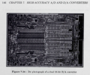
Not sure if this has already been posted here. I found this thesis by Rudy J. van de Plassche (designer of the TDA1540 and 1541). Excellent read. Filesize 80MB.
https://repository.tudelft.nl/islan...61a-9fce-b0c2e3b6f99f/datastream/OBJ/download
Thanks,
Alex
https://repository.tudelft.nl/islan...61a-9fce-b0c2e3b6f99f/datastream/OBJ/download
Thanks,
Alex
Attachments
1541 DAC
Good morning,
John, is this what you had announced some time ago? Is this flowing into a DIY 1541 DAC incl. PCB?
Ernst
Good morning,
John, is this what you had announced some time ago? Is this flowing into a DIY 1541 DAC incl. PCB?
Ernst
Hi, John. Some time ago you explained the 50Hz DEM-clock, but to my perception the scoop-images you've shown indicate an almost shutting down of the DEM functionality. Or am I wrong?Hi sumotan,
This is caused by the I2S interface and the 200 KHz DEM clock, that's why I suggested to run the TDA1541A in simultaneous mode with 25% data density and use 50Hz DEM clock.
This reduces on-chip ground-bounce to almost zero when the outputs are latched, so it results in lowest obtainable jitter with this chip.
In the meantime I still prefer the DEM-clock at approx. 1Mhz.
Or am I wrong?
I think you are right.
This 50-KHz DEM generator castrate the very idea of DEM, since the currents of the active divider do not alternate within one sample. But John does not pay attention to this. He believes that it is more important to ensure low switching noise. With the same success you can just shut the DEM generator.
In my estimation, the oscillator frequency should be of the order of 700-800 kHz. This frequency should be selected by ear.
- Home
- Source & Line
- Digital Line Level
- Building the ultimate NOS DAC using TDA1541A