and the MSB (pin 13) has a 4uF Solen FC propylene cap (big ugly sucker!)
Unfortunately there is not such an animal on the market right now, may be 2 x 2.2 uf will do ?
Cheers
silvered mica SMDs
John
Where do you get the silvered mica SMDs? Cant seem to find them anywhere, ie Mouser or Digikey.
thanks
JimS
John
Where do you get the silvered mica SMDs? Cant seem to find them anywhere, ie Mouser or Digikey.
thanks
JimS
Sorry Ignat,
I tried both 3.9uF and a pair of the 2uF - the 3.9 were pretty close at 3.96 and 3.98 and I got a few 2.0uFs that added up in // to 4.06, 4.03uF - at 4.1uF, the bass became slightly 'looser' and the range seemed to be about 3.6 <-> 4.1uF - I used headphones for sorting this out, as was easier to hear differences
Remember, this is in my particular system and after my fiddling etc, etc so it might not be the same with you - the 2.0uF ones are a lot thinner and maybe easier to fit - "icelake-audio' on eBay has some, and they're fairly close tolerance - for some reason they take about 40 hours to come good and bass was pretty much okay after about 100hrs use - weird idea for some people but just like 'running in' the new car, etc.
... and you DO need to be a bit patient with this dac chip - no need to rush about looking for instant perfection - the 'doing' (trial/error testing and your own ears) is the learning and especially about gaining better 'listening skills'
All the best ....
John
Where do you get the silvered mica SMDs? Cant seem to find them anywhere, ie Mouser or Digikey.
thanks
JimS
digi mica caps (they were with the PTFE caps )
Product Index > Capacitors > Mica and PTFE Capacitors
Invalid Request
... and you DO need to be a bit patient with this dac chip - no need to rush about looking for instant perfection - the 'doing' (trial/error testing and your own ears) is the learning and especially about gaining better 'listening skills'
All the best ....
Thanks , agreed, I have calmed down already. One day will try your recipe, for the timebeing listening with no caps.
Cheers,
Sorry for breaking into this discussion.Hi Ceglar,
I suggest to use small SMD MELF or thin film resistors, 1206 or 805 size and use shortest possible wiring in order to minimise EMI pick-up.
I now use a 100pF SMD mica cap from Cornell Dubilier
This capacitor should be placed as close to pin 16 & 17 as possible.
I attached a picture of the SD2-player prototype.
You can see the two MELF resistors and the mica cap close to pins 16 & 17.
First I'd like to get a clear picture regarding the DEM modification with regard to the situation in my CD player (using a TDA1541A S1 and a standard noise source =SAA7220).
Capacitor value
In the schematic a 680pf cap is indicated in the Service Manual, where a 470pf is suggested in the datasheet. Does that mean that the DEM-clock is running at a lower frequency than required?
You yourself indicate changing that cap value from 470pf to 100pf, correct?
Would it be an option to implement the 100pf cap together with the resistors instead of the current 680pf cap or would it be wiser to use a 470pf cap?
Resistor value
What I understood is that both pins 16 and 17 are pulled to the -15V rails using 6k8 ohms resistors. I have no cause to doubt the correctness of that value, but could you please indicate how this value came to be? I'd like to learn, you know?
Thanks in advance for answering my questions.
Cheers, Edwin
First I'd like to get a clear picture regarding the DEM modification
You yourself indicate changing that cap value from 470pf to 100pf, correct?
Would it be an option to implement the 100pf cap together with the resistors instead of the current 680pf cap or would it be wiser to use a 470pf cap?
Hi Edwin,
IMHO - You are expecting some definite replies from people who will never give you an yes or not answer /this is the most important and attractive trend in this forum/ but give you a direction of thinking and experimenting. Therefore I believe you have to patiently just read about the experience they kindly share and decide by yourself what SOUND you like better.
I have never tried 100 pf option but will try just for curiosity 🙂
Cheers,
Ignat
Thanks Ignat,Hi Edwin,First I'd like to get a clear picture regarding the DEM modification
You yourself indicate changing that cap value from 470pf to 100pf, correct?
Would it be an option to implement the 100pf cap together with the resistors instead of the current 680pf cap or would it be wiser to use a 470pf cap?
IMHO - You are expecting some definite replies from people who will never give you an yes or not answer /this is the most important and attractive trend in this forum/ but give you a direction of thinking and experimenting. Therefore I believe you have to patiently just read about the experience they kindly share and decide by yourself what SOUND you like better.
I have never tried 100 pf option but will try just for curiosity 🙂
Cheers,
Ignat
Perhaps my questions ask too much for a yes/no like answer, but I guess I'm a bit too insecure to rip open a good CD player and stick the soldering-iron into it. So that's why I am probing for some additional knowledge and hope that the regular posters in this thread are willing to share their knowledge in a way I can digest. That's also the reason for my way of asking...
The 100pf seems a bit too scary for me right now, but if there are good enough reasons for trying... why not 😉
Sorry for breaking into this discussion.
First I'd like to get a clear picture regarding the DEM modification with regard to the situation in my CD player (using a TDA1541A S1 and a standard noise source =SAA7220).
Capacitor value
In the schematic a 680pf cap is indicated in the Service Manual, where a 470pf is suggested in the datasheet. Does that mean that the DEM-clock is running at a lower frequency than required?
You yourself indicate changing that cap value from 470pf to 100pf, correct?
Would it be an option to implement the 100pf cap together with the resistors instead of the current 680pf cap or would it be wiser to use a 470pf cap?
Resistor value
What I understood is that both pins 16 and 17 are pulled to the -15V rails using 6k8 ohms resistors. I have no cause to doubt the correctness of that value, but could you please indicate how this value came to be? I'd like to learn, you know?
Thanks in advance for answering my questions.
Cheers, Edwin
Hi Edwin,
I'm not John but my interest lies exactly where yours seems to at the moment. Of course changing the value of cap across the DEM pins changes the DEM frequency.. and heres the thing… adding those two 6k8 resistors further changes the frequency, as evidenced by Ryanj's oscilloscope screen shots (and videos). IIRC it shifted his 88kHz up to ~120kHz.. which is quite some difference.
Whens someone who knows more about this stuff than we do is able to comment, I'd be very keen to learn the reasons for this.
Shane
Whens someone who knows more about this stuff than we do is able to comment, I'd be very keen to learn the reasons for this.

What DEM approach?.. this is the issue.. no one knows whats going on !!
In retrospect, the DEM cap across 16,17's usefulness is limited by the values of DEM decoupling caps, and also the ratio of the sampling frequency (say WS) to that DEM frequency. Its a juggling act.. lock in a sampling frequency, 4 to 8 times that for fDEM and make sure the decoupling caps (x14) are well suited - seems to be about the most solid reasoning. (from me, who is not so solid).
It had been previously mentioned that tying 16 and 17 to -15V via some value of resistance 'stopped' the internal oscillator - and this was all to do with external DEM clocking and or synching schemes, which is clearly (?) not the case here.
In the end, I'm residing (rent free) with the fact that there are some suggesting confusing info in order to propel the idea of some mystical and magical formula which aid their commercial products.
IMHO Pedja Rogic and Audial is about the only place that has shared more than enough, and build to openly shared principles.
And with regard to dividing BCK and synching to that (all for NON-OS) why not just multiply WS instead, assuming jitter spec for the divide/multi chips would be the same/similar. At least with the latter scenario.. if you chose to upsample (PC) with 1541A in simultaneous mode.. the fDEM could track nicely with WS in the 4:1 ratio (read that correctly) as outlined by the data-sheet supplement.
I need to take up golf.. or buy a bar and grill on a tropical island with sandy beaches hammocks, open tables and something like a mono Altec 604 fed with a decent amp and 1541A.
Donations?.. 50% can go to Pedjas organised charity..
Ok. Forget the golf part… I don't got the pants or the patience..
Shane
Attachments
Last edited:
Yes, you only have to add two 6K8 resistors to the existing timing cap of 470pF. This will greatly reduce the high level of deterministic jitter on the DEM oscillator as soon as audio data is sent to the TDA1541A.
Hi John,
I have done that and removed ALL 14 decoupling caps - will listen
several days but first impression is quite promising. The resistors are there as you suggested-on the chip's legs - as small as possible.
Thanks,
Ignat
Attachments

Hi Ceglar,
DEM (Dynamic Element Matching) is a technique to obtain highly accurate bit currents from circuits that have tolerances. This eliminates the need for expensive LASER trimming. Other advantage is that as DAC chips age (and tolerances increase) the DEM circuit will maintain high accuracy over a very long time period.
In the TDA1541A the 6 MSBs are divided from a reference current source using DEM. The remaining 10 bits are divided using passive current dividers only. So a reference current is divided into 16 binary weighted (1, 2, 4, 8, 16, 32 and so on) DC bit currents.
One can read in the TDA1540 datasheet how this DEM circuit works (attached pdf). I suggest to read it first
DEM clock frequency is set by an external timing cap (datasheet value = 470pF). Ripple on the active divider outputs equals f DEM.
So with 200KHz DEM clock we have 200KHz ripple frequency. The remark in the datasheet that outputs that are composed of two summed currents has lower ripple frequency is wrong. Practical measurements on many different TDA1541A chips showed this.
The DEM circuit needs 4 DEM clock pulses in order to average between 4 almost equal input currents from the passive divider that drives the DEM circuit.
When f DEM and WS frequency are roughly the same (176 KHz @ 4 * oversampling and 200 KHz DEM clock rate) it is essential to filter out this ripple current with the 14 external filter caps. This is necessary as the DEM circuit cannot complete a full DEM cycle within one sample period.
When f DEM roughly equals WS and no filter caps are used, we get a different bit current for the same bit after every DEM clock pulse and this causes bit errors and distortion.
When f DEM frequency is at least 4 times higher than WS, the filter caps can be omitted as a complete DEM cycle is completed within one sample period.
Running TDA1541A in NOS and using 200KHz or higher DEM clock frequency allows the DEM cycle to complete within one sample. So oshifis remark to omit the filter caps is valid. The 200 KHz ripple is well outside the audio spectrum and thus inaudible, however, SN ratio gets slightly worse as a result of switching spikes and ripple that are not filtered out.
In the final UD2 and SD2-player I use 900 KHz DEM clock rate with NOS. This means that I can complete 5 DEM cycles during one sample and I could get away without using filter caps. But I added 330nF filter caps (that result in extremely low ripple and switching noise with this DEM frequency) in order to maximise SN ratio.
DEM relies on -exactly- equal time intervals between subsequent DEM clock pulses. Since this cannot be realised in practice, second best is only allowing small amount of -random- jitter on the DEM oscillator.
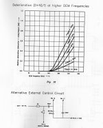
The big problem with the TDA1541A is that the DEM clock gets frequency modulated by the DATA content by means of the locking effect. The locking effect occurs when two almost equal frequencies lock and there is sufficient crosstalk between both signals. So one signal “pulls” the other. With the TDA1541A this effect results in high deterministic jitter on the DEM clock, resulting distortion.
By adding two 6K8 resistors the trigger threshold level can be manipulated and the DEM clock signal amplitude is increased from 1Vpp to 3Vpp. This makes it far less sensitive to interference and deterministic jitter and noise on the DEM clock can be greatly reduced. This is -essential- for highest bit accuracy.
For those who only want to know component values:
Dem timing cap value: 100pF (approx. 900 KHz DEM clock rate).
Filter cap (14 *) value: 330nF SMD 1206 film (make sure to use shortest possible traces / wiring!).
Resistor value (for 3Vpp DEM clock signal amplitude): 6K8.
Whens someone who knows more about this stuff than we do is able to comment, I'd be very keen to learn the reasons for this.
DEM (Dynamic Element Matching) is a technique to obtain highly accurate bit currents from circuits that have tolerances. This eliminates the need for expensive LASER trimming. Other advantage is that as DAC chips age (and tolerances increase) the DEM circuit will maintain high accuracy over a very long time period.
In the TDA1541A the 6 MSBs are divided from a reference current source using DEM. The remaining 10 bits are divided using passive current dividers only. So a reference current is divided into 16 binary weighted (1, 2, 4, 8, 16, 32 and so on) DC bit currents.
One can read in the TDA1540 datasheet how this DEM circuit works (attached pdf). I suggest to read it first
DEM clock frequency is set by an external timing cap (datasheet value = 470pF). Ripple on the active divider outputs equals f DEM.
So with 200KHz DEM clock we have 200KHz ripple frequency. The remark in the datasheet that outputs that are composed of two summed currents has lower ripple frequency is wrong. Practical measurements on many different TDA1541A chips showed this.
The DEM circuit needs 4 DEM clock pulses in order to average between 4 almost equal input currents from the passive divider that drives the DEM circuit.
When f DEM and WS frequency are roughly the same (176 KHz @ 4 * oversampling and 200 KHz DEM clock rate) it is essential to filter out this ripple current with the 14 external filter caps. This is necessary as the DEM circuit cannot complete a full DEM cycle within one sample period.
When f DEM roughly equals WS and no filter caps are used, we get a different bit current for the same bit after every DEM clock pulse and this causes bit errors and distortion.
When f DEM frequency is at least 4 times higher than WS, the filter caps can be omitted as a complete DEM cycle is completed within one sample period.
Running TDA1541A in NOS and using 200KHz or higher DEM clock frequency allows the DEM cycle to complete within one sample. So oshifis remark to omit the filter caps is valid. The 200 KHz ripple is well outside the audio spectrum and thus inaudible, however, SN ratio gets slightly worse as a result of switching spikes and ripple that are not filtered out.
In the final UD2 and SD2-player I use 900 KHz DEM clock rate with NOS. This means that I can complete 5 DEM cycles during one sample and I could get away without using filter caps. But I added 330nF filter caps (that result in extremely low ripple and switching noise with this DEM frequency) in order to maximise SN ratio.
DEM relies on -exactly- equal time intervals between subsequent DEM clock pulses. Since this cannot be realised in practice, second best is only allowing small amount of -random- jitter on the DEM oscillator.
The big problem with the TDA1541A is that the DEM clock gets frequency modulated by the DATA content by means of the locking effect. The locking effect occurs when two almost equal frequencies lock and there is sufficient crosstalk between both signals. So one signal “pulls” the other. With the TDA1541A this effect results in high deterministic jitter on the DEM clock, resulting distortion.
By adding two 6K8 resistors the trigger threshold level can be manipulated and the DEM clock signal amplitude is increased from 1Vpp to 3Vpp. This makes it far less sensitive to interference and deterministic jitter and noise on the DEM clock can be greatly reduced. This is -essential- for highest bit accuracy.
For those who only want to know component values:
Dem timing cap value: 100pF (approx. 900 KHz DEM clock rate).
Filter cap (14 *) value: 330nF SMD 1206 film (make sure to use shortest possible traces / wiring!).
Resistor value (for 3Vpp DEM clock signal amplitude): 6K8.
Attachments
Last edited:
Thanks Ceglar for the book jpeg pic and answer 🙂
.
Thanks EC, I am trying to prepare some TDA1540.
But I am litle bit confused by the datas...
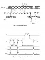
1. Is the format of input signals for TDA1541 same like for TDA1541A in Simultaneous mode, except of word bits 14bit?
2. Is the SCK (BCK) inverted, compared to TDA1541A?
in TDA1540 datas marked as -CP?
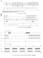
3. could You please draw a logic timing of the 3 line input bus for TDA1540,
because it is pretty unclear in the pdf...
sorry for multi Q 🙂
.
Thanks EC, I am trying to prepare some TDA1540.
But I am litle bit confused by the datas...
1. Is the format of input signals for TDA1541 same like for TDA1541A in Simultaneous mode, except of word bits 14bit?
2. Is the SCK (BCK) inverted, compared to TDA1541A?
in TDA1540 datas marked as -CP?
3. could You please draw a logic timing of the 3 line input bus for TDA1540,
because it is pretty unclear in the pdf...
sorry for multi Q 🙂
Hi Ceglar,
DEM (Dynamic Element Matching) is a technique to obtain highly accurate bit currents from circuits that have tolerances. This eliminates the need for expensive LASER trimming. Other advantage is that as DAC chips age (and tolerances increase) the DEM circuit will maintain high accuracy over a very long time period.
John, I enjoyed your thesis.
Unfortunately, this did not address the question nor the core issue.
Regards,
Shane
Last edited:
- Home
- Source & Line
- Digital Line Level
- Building the ultimate NOS DAC using TDA1541A