John, I lost a bit track of your project (I was probably to busy with a certain dac chip )
)
Did you entirely move away from USB ?
I have build a few iterations of the PCM 2707 in self or bus powerd
mode, but they all are not as good sounding as the EMU 0404 USB.
I don't know why the EMU sounds better. John Svensson says the EMU
has very low jitter and Gordon Rankin thinks the asynchronous PCM
transfer is making a difference. It might be the combination of the two
that makes for the superior sound of the EMU.
I would really like to get away from the EMU as the PCM2707 is small
enough to integrate it into a one box solution to avoid long signal
path.
Was it a notable step up when you went differential from the 2707 to
the dac with the WS, BCK, and DATA signals?
Greets,
Klaus
)Did you entirely move away from USB ?
I have build a few iterations of the PCM 2707 in self or bus powerd
mode, but they all are not as good sounding as the EMU 0404 USB.
I don't know why the EMU sounds better. John Svensson says the EMU
has very low jitter and Gordon Rankin thinks the asynchronous PCM
transfer is making a difference. It might be the combination of the two
that makes for the superior sound of the EMU.
I would really like to get away from the EMU as the PCM2707 is small
enough to integrate it into a one box solution to avoid long signal
path.
Was it a notable step up when you went differential from the 2707 to
the dac with the WS, BCK, and DATA signals?
Greets,
Klaus
Hi Radian,
I stopped using USB when the update to iTunes7 caused significant degraded sound quality through USB (and built-in Toslink). So I started using an AE module with Toslink that did perform well (I used a CD player with Toslink output as reference, using the same recording). The cause for this sound quality degradation was non-bit-perfect playback.
However, iTunes8 doesn't seem to have this problem anymore. So I could now use both iMac Toslink output or USB again.
Since I am convinced of the necessity of full galvanic insulation without slightest coupling capacity, I used a PCM2706, configured for SPDIF out (on I2S DATA pin), and connected a Toslink optical transmitter. This works fine too, and it enables to connect the DI DACs to USB if required.
The "poor sound quality" appears to be caused by DAC jitter sensitivity. I was often convinced that my DI DACs blocked source jitter (reclocker and VCXO / PLL) but it turned out that it still passed source jitter, despite all effort.
Other USB audio receiver chips may have a different jitter spectrum / amplitude, that could result in less sound quality degradation. It's probably not caused by data corruption.
This means that when a DAC has near 100% source jitter blocking, and it doesn't receive noise through either a coupling transformer or direct galvanic link, it will perform nearly identical, regardless of USB / SPDIF receiver used, provided data remains bit-perfect.
The DI DACs now have a microcontroller-based precision frequency tracker. The DAC chips and SPDIF receiver (slave-clock mode) are directly clocked by the masterclock (no reclocking). The clock distribution path is highly tuned (using multiple UHS clock buffers and multiple damping resistors), this is required to maintain a low jitter masterclock when all loads are attached.
The tracker measures both source and masterclock, and adjusts the masterclock for close match. The masterclock is a PXO (programmable Crystal Oscillator) with 10 bit (0.19ppm) resolution and +/- 100ppm pulling range. Adjustments are only allowed with 2 second intervals (meanwhile the SPDIF buffer will compensate for minor phase differences). Due to this very low correction interval (0.5 Hz) source jitter above 0.5 Hz (entire audio range and up) is almost fully blocked. This means that the DACs are no longer sensitive to any (Toslink) source jitter, even if the jitter amplitude of these sources is in the nanosecond range. I verified this by comparing both a 10 meter and a 1.5 meter Toslink interlink, sound quality didn't change at all.
DATA = DATA, no matter what interface is used, as long as the data is not corrupted. That's the whole point of using digital data.
If there are still differences in sound quality, despite correct data, it's caused by either DAC jitter sensitivity, or by interference originating from the source, reaching the DAC electronics, causing unwanted inter-modulation, or both.
Yes, because by using differential buffers, the GND connection between both PCM2707 and DAC could be left out. I later used high-speed opto-couplers for BCK, DATA, and WS signals that were derived from the PCM2706 (UTOS module). But I think it's most practical to convert USB to Toslink as this will provide excellent galvanic insulation, the DATA won't change whether I2S or SPDIF is used. This however requires a DAC that has near 100% source jitter blocking. If the connected DAC is sensitive to jitter, the sound quality has to be "tuned" manipulating digital audio receiver / interlink / DAC combination. I personally don't think this is the best way to go.
Did you entirely move away from USB ?
I have build a few iterations of the PCM 2707 in self or bus powerd
mode, but they all are not as good sounding as the EMU 0404 USB.
I stopped using USB when the update to iTunes7 caused significant degraded sound quality through USB (and built-in Toslink). So I started using an AE module with Toslink that did perform well (I used a CD player with Toslink output as reference, using the same recording). The cause for this sound quality degradation was non-bit-perfect playback.
However, iTunes8 doesn't seem to have this problem anymore. So I could now use both iMac Toslink output or USB again.
Since I am convinced of the necessity of full galvanic insulation without slightest coupling capacity, I used a PCM2706, configured for SPDIF out (on I2S DATA pin), and connected a Toslink optical transmitter. This works fine too, and it enables to connect the DI DACs to USB if required.
The "poor sound quality" appears to be caused by DAC jitter sensitivity. I was often convinced that my DI DACs blocked source jitter (reclocker and VCXO / PLL) but it turned out that it still passed source jitter, despite all effort.
Other USB audio receiver chips may have a different jitter spectrum / amplitude, that could result in less sound quality degradation. It's probably not caused by data corruption.
This means that when a DAC has near 100% source jitter blocking, and it doesn't receive noise through either a coupling transformer or direct galvanic link, it will perform nearly identical, regardless of USB / SPDIF receiver used, provided data remains bit-perfect.
The DI DACs now have a microcontroller-based precision frequency tracker. The DAC chips and SPDIF receiver (slave-clock mode) are directly clocked by the masterclock (no reclocking). The clock distribution path is highly tuned (using multiple UHS clock buffers and multiple damping resistors), this is required to maintain a low jitter masterclock when all loads are attached.
The tracker measures both source and masterclock, and adjusts the masterclock for close match. The masterclock is a PXO (programmable Crystal Oscillator) with 10 bit (0.19ppm) resolution and +/- 100ppm pulling range. Adjustments are only allowed with 2 second intervals (meanwhile the SPDIF buffer will compensate for minor phase differences). Due to this very low correction interval (0.5 Hz) source jitter above 0.5 Hz (entire audio range and up) is almost fully blocked. This means that the DACs are no longer sensitive to any (Toslink) source jitter, even if the jitter amplitude of these sources is in the nanosecond range. I verified this by comparing both a 10 meter and a 1.5 meter Toslink interlink, sound quality didn't change at all.
John Svensson says the EMU
has very low jitter and Gordon Rankin thinks the asynchronous PCM
transfer is making a difference. It might be the combination of the two
that makes for the superior sound of the EMU.
DATA = DATA, no matter what interface is used, as long as the data is not corrupted. That's the whole point of using digital data.
If there are still differences in sound quality, despite correct data, it's caused by either DAC jitter sensitivity, or by interference originating from the source, reaching the DAC electronics, causing unwanted inter-modulation, or both.
Was it a notable step up when you went differential from the 2707 to
the dac with the WS, BCK, and DATA signals?
Yes, because by using differential buffers, the GND connection between both PCM2707 and DAC could be left out. I later used high-speed opto-couplers for BCK, DATA, and WS signals that were derived from the PCM2706 (UTOS module). But I think it's most practical to convert USB to Toslink as this will provide excellent galvanic insulation, the DATA won't change whether I2S or SPDIF is used. This however requires a DAC that has near 100% source jitter blocking. If the connected DAC is sensitive to jitter, the sound quality has to be "tuned" manipulating digital audio receiver / interlink / DAC combination. I personally don't think this is the best way to go.
Bit off topic but...
Does anybody have an idea why usually the most stupid people are laughing most loudly ? (
 )
)
Perhaps because they have nothing to say
Does anybody have an idea why usually the most stupid people are laughing most loudly ? (
Perhaps because they have nothing to say
Hi,
I had an email exchange with Doede Douma (DDDAC1543) about the possibillity of clocking the PCM2707 with an external Clock.
I asked him if its possible to reclock the PCM2707 using some capacity diodes or a simple adjustable crystal oscillator for the mainclock of the USB Receiver with a PLL to let the wordclock, which comes out of the PCM2707 lock onto the master Wordclock from a divider of an X0 clock. then, both clocks would be synchronized and I would get the fewest possible jitter, as the X0 is directly clocking the DAC-Chip.
That would only work of course if the BCK and WS is depending on the mainclock.
He then suggested, I should look at this thread, because you did something similar, but I cant find any text or schematic about such a thing.
I wouldn't even need a schematic, just some word about if its possible, so I don't have to put a lot of money and work into something which wouldn't have worked in the first place.
BTW: Is out there any USB receiver chip which accepts an external clock without such tricks?
Hi Dorsal!
The PCM2706/7, 12 MHz crystal oscillator is mainly used for USB communication and on-chip timing. The source (computer) will dictate average sampling rate. Changing the 12 MHz crystal oscillator frequency has no effect on BCK frequency.
The PCM2706/7 only runs in master mode, meaning that it can only output MCLK, BCK and WS timing signals.
There is a simple way around this, configure the PCM2706/7 for SPDIF output (on DATA out pin), and connect a Toslink transmitter to this pin. The USB receiver Toslink output can now be connected to a Toslink SPDIF receiver that can run in slave clock mode. The use of Toslink guarantees perfect galvanic insulation with zero coupling capacity in order to block all unwanted signal current loops (ground loops) between both source (computer) and DAC. Suitable receivers are CS8412, CS8414 and CS8416 for example.
When using the DDDAC DAC, it should be possible to configure the existing USB receiver to output SPDIF on the DATA output pin. Refer to PCM2707 datasheet for details. This SPDIF signal can now be fed to the existing SPDIF receiver module that runs in slave-clock mode. Galvanic insulation can now easily be provided by using both a Toslink transmitter and receiver pair.
Now both DAC chips, and SPDIF receiver are still directly clocked by the masterclock (and receive a low-jitter clock) while accepting digital audio data from USB, routed via SPDIF.
I had an email exchange with Doede Douma (DDDAC1543) about the possibillity of clocking the PCM2707 with an external Clock.
The PCM2706/7, 12 MHz crystal oscillator is mainly used for USB communication and on-chip timing. The source (computer) will dictate average sampling rate. Changing the 12 MHz crystal oscillator frequency has no effect on BCK frequency.
The PCM2706/7 only runs in master mode, meaning that it can only output MCLK, BCK and WS timing signals.
There is a simple way around this, configure the PCM2706/7 for SPDIF output (on DATA out pin), and connect a Toslink transmitter to this pin. The USB receiver Toslink output can now be connected to a Toslink SPDIF receiver that can run in slave clock mode. The use of Toslink guarantees perfect galvanic insulation with zero coupling capacity in order to block all unwanted signal current loops (ground loops) between both source (computer) and DAC. Suitable receivers are CS8412, CS8414 and CS8416 for example.
When using the DDDAC DAC, it should be possible to configure the existing USB receiver to output SPDIF on the DATA output pin. Refer to PCM2707 datasheet for details. This SPDIF signal can now be fed to the existing SPDIF receiver module that runs in slave-clock mode. Galvanic insulation can now easily be provided by using both a Toslink transmitter and receiver pair.
Now both DAC chips, and SPDIF receiver are still directly clocked by the masterclock (and receive a low-jitter clock) while accepting digital audio data from USB, routed via SPDIF.
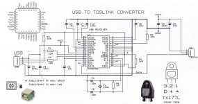
I attached a schematic for a simple USB to Toslink converter. The TX177L Toslink transmitter can be ordered at Farnell (P/N 1225772). The circuit is bus-powered (receives power supply from USB). It should be possible to make a miniature version approx. the size of an USB stick, it could then be directly plugged into an USB socket having shortest possible USB interlink.
I am using a similar circuit to connect both DI4MJ and DI4T to USB audio sources during testing.
I have to point out that the USB audio source needs to provide bit-perfect playback for best results.
The PCM2706/7 has pin 9 (FSEL) tied to VDD in order to select SPDIF output. The SPDIF signal will appear on pin 17(DATA).
Attachments
-ecdesigns- said:It should be possible to make a miniature version approx. the size of an USB stick, it could then be directly plugged into an USB socket having shortest possible USB interlink. [/B]
I am interested in a small usb stick version if you plan to build it.
-ecdesigns- said:Hi Radian,
I stopped using USB when the update to iTunes7 caused significant degraded sound quality through USB (and built-in Toslink). So I started using an AE module with Toslink that did perform well (I used a CD player with Toslink output as reference, using the same recording). The cause for this sound quality degradation was non-bit-perfect playback.
However, iTunes8 doesn't seem to have this problem anymore. So I could now use both iMac Toslink output or USB again.
Since I am convinced of the necessity of full galvanic insulation without slightest coupling capacity, I used a PCM2706, configured for SPDIF out (on I2S DATA pin), and connected a Toslink optical transmitter. This works fine too, and it enables to connect the DI DACs to USB if required.
The "poor sound quality" appears to be caused by DAC jitter sensitivity. I was often convinced that my DI DACs blocked source jitter (reclocker and VCXO / PLL) but it turned out that it still passed source jitter, despite all effort.
Other USB audio receiver chips may have a different jitter spectrum / amplitude, that could result in less sound quality degradation. It's probably not caused by data corruption.
This means that when a DAC has near 100% source jitter blocking, and it doesn't receive noise through either a coupling transformer or direct galvanic link, it will perform nearly identical, regardless of USB / SPDIF receiver used, provided data remains bit-perfect.
The DI DACs now have a microcontroller-based precision frequency tracker. The DAC chips and SPDIF receiver (slave-clock mode) are directly clocked by the masterclock (no reclocking). The clock distribution path is highly tuned (using multiple UHS clock buffers and multiple damping resistors), this is required to maintain a low jitter masterclock when all loads are attached.
The tracker measures both source and masterclock, and adjusts the masterclock for close match. The masterclock is a PXO (programmable Crystal Oscillator) with 10 bit (0.19ppm) resolution and +/- 100ppm pulling range. Adjustments are only allowed with 2 second intervals (meanwhile the SPDIF buffer will compensate for minor phase differences). Due to this very low correction interval (0.5 Hz) source jitter above 0.5 Hz (entire audio range and up) is almost fully blocked. This means that the DACs are no longer sensitive to any (Toslink) source jitter, even if the jitter amplitude of these sources is in the nanosecond range. I verified this by comparing both a 10 meter and a 1.5 meter Toslink interlink, sound quality didn't change at all.
DATA = DATA, no matter what interface is used, as long as the data is not corrupted. That's the whole point of using digital data.
If there are still differences in sound quality, despite correct data, it's caused by either DAC jitter sensitivity, or by interference originating from the source, reaching the DAC electronics, causing unwanted inter-modulation, or both.
Yes, because by using differential buffers, the GND connection between both PCM2707 and DAC could be left out. I later used high-speed opto-couplers for BCK, DATA, and WS signals that were derived from the PCM2706 (UTOS module). But I think it's most practical to convert USB to Toslink as this will provide excellent galvanic insulation, the DATA won't change whether I2S or SPDIF is used. This however requires a DAC that has near 100% source jitter blocking. If the connected DAC is sensitive to jitter, the sound quality has to be "tuned" manipulating digital audio receiver / interlink / DAC combination. I personally don't think this is the best way to go.
Thanks John,
it is absolutely beyond me how all this format change can be
without sonic penalty. I2S to Toslink to spdiff to I2S to analog.
I got a few ISO150 chips from TI that I will try to implement
for galvanic insulation and I will see how it stacks up to differential.
Greets,
Klaus
Re: Bit off topic but...
There are no stupid people, because others have areas of interests and social skills were they get us laughing very loud.
Greets,
Klaus
Bernhard said:Does anybody have an idea why usually the most stupid people are laughing most loudly ? ()
Perhaps because they have nothing to say
There are no stupid people, because others have areas of interests and social skills were they get us laughing very loud.
Greets,
Klaus
Hi Radian,
The DATA is most important, you wouldn't want to know how data is distributed over the internet, still the data arrives intact. That's the advantage of digital data transfers. The received data can be verified by looping it back to a Toslink input (my powermac G5 has one), and performing a file comparison.
The USB > Toslink > I2S conversion still provides exactly the same data as with USB > I2S, SPDIF > I2S or direct I2S from a transport. There is a large margin for error before data corruption occurs.
The only difference is both jitter amplitude and spectrum. The multiple conversions using (SpAct) PLLs do affect both jitter spectrum and amplitude of course. But this is basically irrelevant because a well designed DAC circuit should be able to block this source jitter. Also consider that the majority of (external) DACs are sensitive to source jitter, and usually suffer from unwanted inter-modulations between digital, analogue and power supply interference currents. In such case the sound quality can be regulated until it matches personal taste, by fiddling with various interfaces, and interlinks.
Low jitter clocks only remain low jitter clocks when running on a super-clean power supply, the clock buffers don't add too much extra jitter, and the attached loads don't increase masterclock jitter. This is much more difficult than it appears, took me ages to figure it out.
You could do a simple test, feed the DAC masterclock with a 4.5 ...4.8V battery power supply (3 x penlight AA alkaline or 4 x NiMH batteries in series) and connect it directly to the pins of the masterclock module.
The 5V mains power supply for the masterclock should be interrupted of course. If this test provides significant improved sound quality, then you have a problem with masterclock power supply and or power supply & GND routing.
Forget it, the ISO150 uses 0.5pF coupling capacitors for data transfer (2 for each channel). You will need 3 channels for I2S, this means 2 x ISO150 and 8 * 0.5pF coupling capacitance between both source and DAC (the unused transceiver also passes HF through 2 x 0.5pF, as HF interference doesn't always follow the traces in the schematics).
Total coupling capacitance for passing unwanted HF interference currents adds up to 4pF. This will nicely flood your DAC with HF interference by providing low impedance path for these HF signal currents.
Been there, done that, the easiest way is just to use Toslink. There is up to a few meters of optical fibre between both source (computer) and DAC. The coupling capacitance of few meters of optical fibre is virtually zero.
If you are thinking of using 3 x Toslink coupling to transport I2S, you can forget that too, the skewing caused by the DATA signal will prevent this from functioning.
it is absolutely beyond me how all this format change can be
without sonic penalty. I2S to Toslink to spdiff to I2S to analog.
The DATA is most important, you wouldn't want to know how data is distributed over the internet, still the data arrives intact. That's the advantage of digital data transfers. The received data can be verified by looping it back to a Toslink input (my powermac G5 has one), and performing a file comparison.
The USB > Toslink > I2S conversion still provides exactly the same data as with USB > I2S, SPDIF > I2S or direct I2S from a transport. There is a large margin for error before data corruption occurs.
The only difference is both jitter amplitude and spectrum. The multiple conversions using (SpAct) PLLs do affect both jitter spectrum and amplitude of course. But this is basically irrelevant because a well designed DAC circuit should be able to block this source jitter. Also consider that the majority of (external) DACs are sensitive to source jitter, and usually suffer from unwanted inter-modulations between digital, analogue and power supply interference currents. In such case the sound quality can be regulated until it matches personal taste, by fiddling with various interfaces, and interlinks.
Low jitter clocks only remain low jitter clocks when running on a super-clean power supply, the clock buffers don't add too much extra jitter, and the attached loads don't increase masterclock jitter. This is much more difficult than it appears, took me ages to figure it out.
You could do a simple test, feed the DAC masterclock with a 4.5 ...4.8V battery power supply (3 x penlight AA alkaline or 4 x NiMH batteries in series) and connect it directly to the pins of the masterclock module.
The 5V mains power supply for the masterclock should be interrupted of course. If this test provides significant improved sound quality, then you have a problem with masterclock power supply and or power supply & GND routing.
I got a few ISO150 chips from TI that I will try to implement
for galvanic insulation and I will see how it stacks up to differential
Forget it, the ISO150 uses 0.5pF coupling capacitors for data transfer (2 for each channel). You will need 3 channels for I2S, this means 2 x ISO150 and 8 * 0.5pF coupling capacitance between both source and DAC (the unused transceiver also passes HF through 2 x 0.5pF, as HF interference doesn't always follow the traces in the schematics).
Total coupling capacitance for passing unwanted HF interference currents adds up to 4pF. This will nicely flood your DAC with HF interference by providing low impedance path for these HF signal currents.
Been there, done that, the easiest way is just to use Toslink. There is up to a few meters of optical fibre between both source (computer) and DAC. The coupling capacitance of few meters of optical fibre is virtually zero.
If you are thinking of using 3 x Toslink coupling to transport I2S, you can forget that too, the skewing caused by the DATA signal will prevent this from functioning.
But using a S/PDIF Receiver Between the USB Receiver and the DAC without clocking the Data synchrone to the masterclock the masterclock, would cause some sample losses or worse.
When the Receiver gets Data from the USB, which has slightly faster, or slower clock, but I force it to output I²S with my own clock it has to run out of sync, or loose some samples or bits (or doubeling them). I can't imagine how synchrone reclocking should work here without the USB Receiver in slave mode.
I know, that slave mode is possible through firewire. Are there any firewire chips available which can possibly be used for DIY?
Hi Dorsal!
The SPDIF receiver buffer will compensate for small frequency differences between source timing and master clock, if the frequency difference gets to big, samples are dropped / repeated. If too many samples are dropped / repeated sequentially, audible clicks or pops will occur. This is best audible (and measurable) when playing back sinewaves.
It doesn't, that's why it's important to synchronize both source and master clock as well. PLLs aren't optimal as source jitter seeps through both phase comparator and loop filter, they also require very low corner frequency for the loop filter, this in turn results in long locking time.
That's why I use a micro controller-based frequency tracker now. It directly programs master clock frequency with approx. 0.19ppm accuracy (10-bit resolution). Corrections are only allowed every 2 seconds. This will basically block source jitter within and beyond the audio range, starting at approx. 0.5 Hz.
This new jitter blocking system is currently being tested in both DI4T and DI4MJ.
But using a S/PDIF Receiver Between the USB Receiver and the DAC without clocking the Data synchrone to the masterclock the masterclock, would cause some sample losses or worse.
The SPDIF receiver buffer will compensate for small frequency differences between source timing and master clock, if the frequency difference gets to big, samples are dropped / repeated. If too many samples are dropped / repeated sequentially, audible clicks or pops will occur. This is best audible (and measurable) when playing back sinewaves.
I can't imagine how synchronous reclocking should work here without the USB Receiver in slave mode.
It doesn't, that's why it's important to synchronize both source and master clock as well. PLLs aren't optimal as source jitter seeps through both phase comparator and loop filter, they also require very low corner frequency for the loop filter, this in turn results in long locking time.
That's why I use a micro controller-based frequency tracker now. It directly programs master clock frequency with approx. 0.19ppm accuracy (10-bit resolution). Corrections are only allowed every 2 seconds. This will basically block source jitter within and beyond the audio range, starting at approx. 0.5 Hz.
This new jitter blocking system is currently being tested in both DI4T and DI4MJ.
I am using a similar circuit to connect both DI4MJ and DI4T to USB audio sources during testing.
What is DI4MJ?
I think I might have a "better" Idea then USB as a connection to my PC.
I'm trying to find a cheap and simple PCI soundcard, which is using a chip that has at least a normal datasheet available.
Then I will try Clock injection as it is done at some CD Player Mods.
PCI should support this and Ill get a perfectly synchronized clock.
As I already planned using a uC for controlling a PGA Volume control and some other things I am very interested in the digital PLL you described. which Oscillator did you use, and is it as low in jitter as an X0 Clock?
DI4MJ
Hi agent.5,
The DI4Mj is the replacement for the DI16.
So I am basically developing only 2 DACs now, the small DI4MJ and the DI4T.
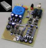
The DI4MJ is based on 4 x TDA1543 in a highly optimized design. I attached a photograph of an early prototype. This DAC is placed in a small DI16 anodized aluminum housing
It's a single-PCB DAC that has power supply integrated and consumes approx. 4 watts in total.
It has an on-board Toslink input and CS8416 receiver that runs in slave-clock mode. the 4 TDA1543 chips perform 4 x interpolation, they run on 4.6V power supply and need no heatsink. The new version has both scrambler and tracker, just like with the DI4T. The power supplies are all filtered using both chokes and supercaps.
All 4 TDA1543 chips have I2S attenuators / bandlimiters installed (8 in total).
The master clock is a discrete low-jitter VCXO that produces 2.8224 MHz and can be varied +/-100ppm with 10-bit resolution. The crystal runs on very low power for lowest jitter. The master clock is buffered by multiple UHS clock buffers, damping resistors are used on all digital outputs to minimize interference.
The I/V conversion is now passive (4 x 110 Ohms) using 2 x Arcol 220R in parallel. Amplification is done with the new discrete high-resolution 4-JFET amplifiers (basically a replica of the new DI4T tube amplifiers), but now using JFETs. The 4-JFET amplifiers have DC-coupled output, so the output coupling caps on the photograph are no longer required.
The DAC also has a remote power on/off option, so it can be switched-on by applying a 5V control signal. The LED indicator on the front panel lights when the tracker has locked.
Hi agent.5,
What is DI4MJ?
The DI4Mj is the replacement for the DI16.
So I am basically developing only 2 DACs now, the small DI4MJ and the DI4T.
The DI4MJ is based on 4 x TDA1543 in a highly optimized design. I attached a photograph of an early prototype. This DAC is placed in a small DI16 anodized aluminum housing
It's a single-PCB DAC that has power supply integrated and consumes approx. 4 watts in total.
It has an on-board Toslink input and CS8416 receiver that runs in slave-clock mode. the 4 TDA1543 chips perform 4 x interpolation, they run on 4.6V power supply and need no heatsink. The new version has both scrambler and tracker, just like with the DI4T. The power supplies are all filtered using both chokes and supercaps.
All 4 TDA1543 chips have I2S attenuators / bandlimiters installed (8 in total).
The master clock is a discrete low-jitter VCXO that produces 2.8224 MHz and can be varied +/-100ppm with 10-bit resolution. The crystal runs on very low power for lowest jitter. The master clock is buffered by multiple UHS clock buffers, damping resistors are used on all digital outputs to minimize interference.
The I/V conversion is now passive (4 x 110 Ohms) using 2 x Arcol 220R in parallel. Amplification is done with the new discrete high-resolution 4-JFET amplifiers (basically a replica of the new DI4T tube amplifiers), but now using JFETs. The 4-JFET amplifiers have DC-coupled output, so the output coupling caps on the photograph are no longer required.
The DAC also has a remote power on/off option, so it can be switched-on by applying a 5V control signal. The LED indicator on the front panel lights when the tracker has locked.
Attachments
Hi Dorsal,
It's no DPLL, but a frequency tracker. When accurately locking on the source clock phase, the lower jitter frequency spectrum of the source is "copied" and transfered to the masterclock.
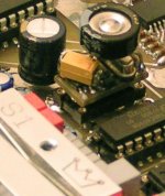
I use a discrete VCXO circuit, the crystal runs on very low power, and the power supply has a special filter on it to emulate a battery power supply. The control voltage input is connected to a 10-bit passive R2R DAC through a low-series capacitance, low-pass filter. The VCXO also has on-board filters for both power supply and voltage control inputs. The masterclock outperforms the standard 0.5ps rms XO clock modules that still produce significant jitter below 10KHz as specified in the datasheet.
I added a close-up of this VCXO, it's a small double-sided PCB with SMD parts on both sides. The 0.1F (100,000uF) supercap is soldered directly to the power supply pins for best performance.
I hope you are not referring to a PGA 3210 semiconductor volume control, tried these and some others like the LM1971 / LM1973. They weren't bad, but clearly degraded sound quality. That's why I am now using a passive resistive attenuator with relays and Vishay Bulk metal foil resistors.
What clock frequency do you plan to use for this uC? It's very likely that any clock frequency that doesn't match the master clock will result in unwanted inter-modulation between both clocks.
I am very interested in the digital PLL you described. which Oscillator did you use, and is it as low in jitter as an X0 Clock?
It's no DPLL, but a frequency tracker. When accurately locking on the source clock phase, the lower jitter frequency spectrum of the source is "copied" and transfered to the masterclock.
I use a discrete VCXO circuit, the crystal runs on very low power, and the power supply has a special filter on it to emulate a battery power supply. The control voltage input is connected to a 10-bit passive R2R DAC through a low-series capacitance, low-pass filter. The VCXO also has on-board filters for both power supply and voltage control inputs. The masterclock outperforms the standard 0.5ps rms XO clock modules that still produce significant jitter below 10KHz as specified in the datasheet.
I added a close-up of this VCXO, it's a small double-sided PCB with SMD parts on both sides. The 0.1F (100,000uF) supercap is soldered directly to the power supply pins for best performance.
As I already planned using a uC for controlling a PGA Volume control
I hope you are not referring to a PGA 3210 semiconductor volume control, tried these and some others like the LM1971 / LM1973. They weren't bad, but clearly degraded sound quality. That's why I am now using a passive resistive attenuator with relays and Vishay Bulk metal foil resistors.
What clock frequency do you plan to use for this uC? It's very likely that any clock frequency that doesn't match the master clock will result in unwanted inter-modulation between both clocks.
Attachments
I guess I could run the uC on the undivided Mainclock Frequency of 8.4672 MHz, because I'll be using an ATMega.
But because I would use the uC only for (nearly) DC in- and outputs I guess shielding it and using a separate Power Supply Line would be enough to prevent interference.
I already thought of a passive volume control (actually I've already got the Reed Relais I planned to use here), but it then seemed like a bit overkill to me, because the stats of the PGA2311 and its brothers aren't that bad. Also, a passive attenuator using Relais has some disadvantages in the usability. The lowest bit Relais die often, as they get switched once for every point of volume. (which would also end in extensive clicking.)
But as I think now, I could pass this problem by a rotary Switch, and a LED Bargraph and some delay in before the setting gets applied.
But thats not important now, because the analogue part of this project is still far in the future.
That frequency tracker is of you is very interesting. I don't know how bad the low frequency jitter of a real bad source is, but this should work with the most of them.
Who wants to use a real bad source anyway. Also this should work very well with the Tent VXCO. I could use two of them then, one for 44,1k and one for 48k. Then I wont use another fixed frequency oscillator for a "real" synchronous path.
Re: DI4MJ
What happened to the DI8M?
I have been out of the forums for a few months.
-ecdesigns- said:Hi agent.5,
The DI4Mj is the replacement for the DI16.
So I am basically developing only 2 DACs now, the small DI4MJ and the DI4T.
What happened to the DI8M?
I have been out of the forums for a few months.
- Home
- Source & Line
- Digital Line Level
- Building the ultimate NOS DAC using TDA1541A