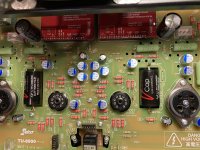
I have Brimar CV4003/6189/12AU7WA
 https://flic.kr/p/2mBnXQj https://www.flickr.com/photos/64593884@N08/
 https://flic.kr/p/2mBqfJb https://www.flickr.com/photos/64593884@N08/
 https://flic.kr/p/2mBrqcy https://www.flickr.com/photos/64593884@N08/
 https://flic.kr/p/2mBnXSd https://www.flickr.com/photos/64593884@N08/
 https://flic.kr/p/2mBnXQj https://www.flickr.com/photos/64593884@N08/
 https://flic.kr/p/2mBqfJb https://www.flickr.com/photos/64593884@N08/
 https://flic.kr/p/2mBrqcy https://www.flickr.com/photos/64593884@N08/
 https://flic.kr/p/2mBnXSd https://www.flickr.com/photos/64593884@N08/
Last edited:
Here is some interesting discussion on OT resistors.
Conclusion, it is there to protect the transformer when Non NFB operation mode and stuff got unhooked suddenly
Resistor across output transformer secondaries? | Page 2 | Audiokarma Home Audio Stereo Discussion Forums
Conclusion, it is there to protect the transformer when Non NFB operation mode and stuff got unhooked suddenly
Resistor across output transformer secondaries? | Page 2 | Audiokarma Home Audio Stereo Discussion Forums
Hi folks, I forgot to put in the vcaps since I was following the manual and soldered in the stock caps. I am guessing I will have to desolder the stock ones and solder in the vcaps from the top to the posts installed on the pcb?
Yes, if you want to stay the closest to the designer intentions. Otherwise , you can keep it as a mean of Bi-cap, but that may change the sound too much. I did remove the stock one when I put in Vcap
I too am having a brain fart. Do I have the v-cap
installed correctly? Outer foil facing anode. Is this right?
I’ve confused myself.
Green is the outer foil which should be closest to ground, and should be connected to "grid side"
@Hifihunter , I noticed your build has TAKMAN TEX resistors. Did you order them separately?
In a moment of weakness early this morning after working long hours yesterday. I ordered a TU8900 kit from Victor. I will be sharing my build here also.
I haven't received the kit yet, I wonder if it is worth upgrading the resistors.
In a moment of weakness early this morning after working long hours yesterday. I ordered a TU8900 kit from Victor. I will be sharing my build here also.
I haven't received the kit yet, I wonder if it is worth upgrading the resistors.
I too am having a brain fart. Do I have the v-cap
installed correctly? Outer foil facing anode.
The outer foil should be connected to the lower impedance node of the two.
In this case, that is the plate.
I ordered Takman from Hifi Collective. They have a good supply of all the values needed. They fit better in this amp than in the 8600.
I’m still confused as to which is best direction for vcap install? I was thinking that the anode of the 12bh7 is the lowest impedance path to ground. Maybe there is some difference of opinion on this. Vcap website says that the green side is the outer foil.
I’m still confused as to which is best direction for vcap install? I was thinking that the anode of the 12bh7 is the lowest impedance path to ground. Maybe there is some difference of opinion on this. Vcap website says that the green side is the outer foil.
The input side of the cap sees the plate and the plate resistor in parallel.
The output side sees the grid resistor (which is much larger).
So the outer foil goes to the plate.
A high impedance circuit node is more sensitive to noise pickup, and the outer foil
(when driven by a lower impedance) helps to shield it.
The output side sees the grid resistor (which is much larger).
So the outer foil goes to the plate.
A high impedance circuit node is more sensitive to noise pickup, and the outer foil
(when driven by a lower impedance) helps to shield it.
Last edited:
Yes. This is what I was thinking. So I think I have them in there the proper direction. I will leave them be. Thank you.
The stock resistor of TU-8900 is KOA. They are very good in sound and quality.
The stock resistor of TU-8600S is a low grade resistor that is why I offer Takman upgrade.
If you have question about your installation, please look at page 26.
PT 7, 8 is innermost foil (the V Cap logo side)
The green lead indicates the outermost foil # 9, 10
V-Cap Audio Capacitor Installation Notes
Ok. I see on page 26 that the output tube has no grid stopper resistor. So maybe I do have the caps backwards. Looks like outer foil needs to face the grid of the output tube in this case.
you can do whatever you want.
i will do the recommendation from vcap
V-Cap Audio Capacitor Installation Notes
i will do the recommendation from vcap
V-Cap Audio Capacitor Installation Notes
